How to build a PICKit3 programming circuit with a PIC microcontroller?
Source: InternetPublisher:黄土马家 Keywords: PIC Microcontroller Updated: 2025/02/18
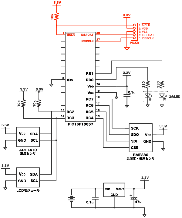
In this article, we mainly explain how to build a PICKit3 programming circuit with a PIC microcontroller. Take the circuit in the figure below as an example. The programming circuit assembled on the breadboard is the red part of the following circuit diagram.
1. PIC microcontroller write pin
The write pin of the PIC microcontroller is located at the end of the host. The name of the write pin may be "PGD/PGC" or "ICSPDAT/ICSPCLK", but both mean the same thing.
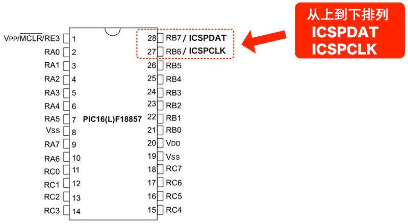
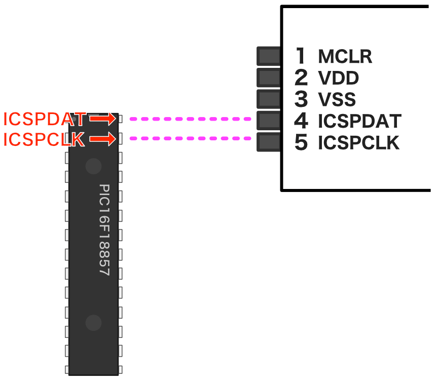
The arrangement of these pins of the PIC16F18857 used this time is as follows.
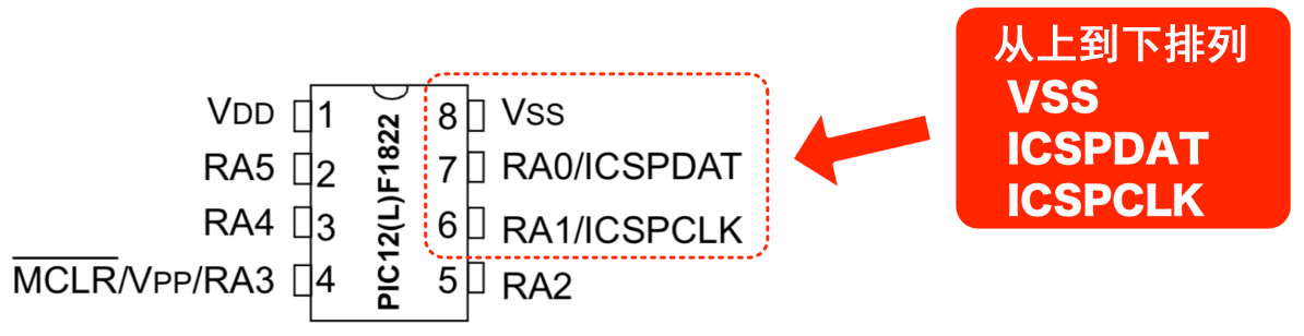
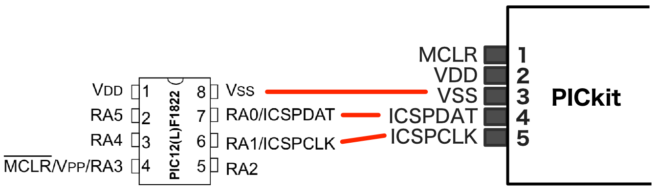
In addition, in the PIC12F1822 used so far, in addition to these two pins, the VSS pin is arranged as follows.
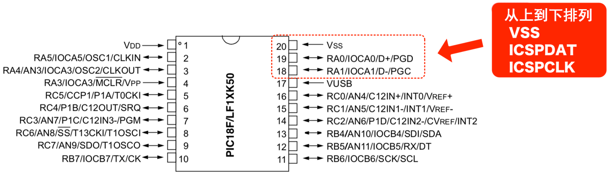
Other PIC microcontrollers (such as PIC18F14K50) are also arranged as follows.
Thus, if the PICKit connector is placed at the edge of the PIC microcontroller, it will be easier to create a programming circuit.
Check PIC16F18857 and align the program writing pins of PIC microcontroller with the connector of PICKit as follows.

Also, take a look at the PIC12F1822, which is suitable for the following situation.
In this way, the program writing pins of the PIC microcontroller match the connector of the PICKit3, making wiring easy. Therefore, we will consider the arrangement of the pin headers to reduce wiring as much as possible.
2. Pin arrangement
The ICSPDAT and ICSPCLK pins of the PIC16F18857 align with the PICKit3 connector.
Also, since pin 6 of the PICKit3 connector and pins 6 to 8 of the PICkit4 are not used, the pin header should be 5-pin and connected on the breadboard as shown below:
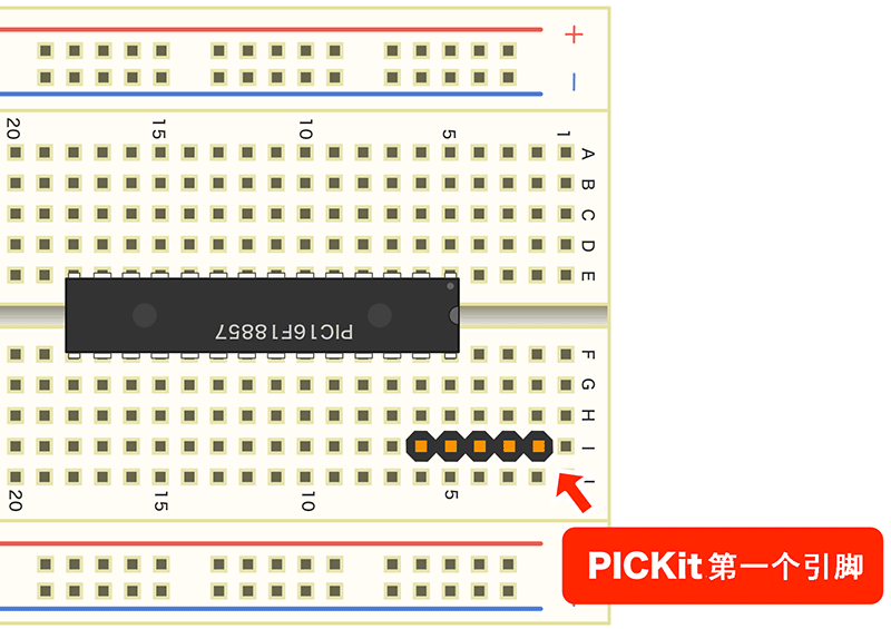
This arrangement eliminates the need for ICPDAT and ICSPCLK wiring. Afterwards, the necessary connections can be made as per the circuit diagram.
3. Breadboard Assembly
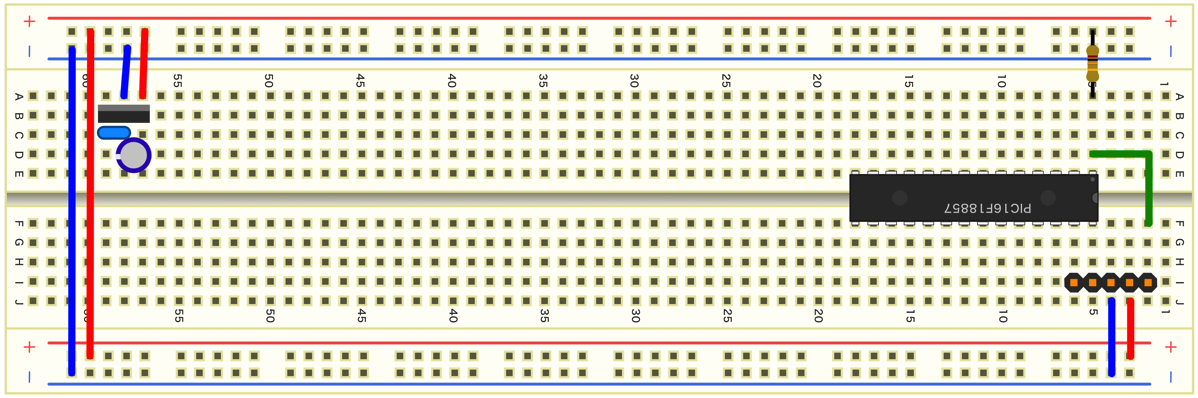
Finally, do the wiring so that you can connect the circuit diagram. The following figure shows the wiring is completed and can be used as a reference.
- How to solve the problem when MAX485/RS485 overheats and stops working when driven by a microcontroller?
- How to build a PICKit3 programming circuit with a PIC microcontroller?
- How to control a bidirectional DC motor using an 8051 microcontroller
- Make an alcohol tester based on 8051 microcontroller
- Introduction to the use of UnoArduSim
- Digital frequency meter made with ATmega8 microcontroller
- Circuit design analysis of smart car image recognition system
- Encodable digital lock circuit diagram
- Use PC’s RS232 port to control LED lights
- SST89C58 electronic disk circuit and code


 京公网安备 11010802033920号