LM337 pin diagram and parameters, LM337 application circuit diagram
Source: InternetPublisher:清宁时光 Keywords: Voltage Regulator LM337 Updated: 2025/02/14
In this post, we will discuss the functionality of an interesting voltage regulator device: the LM337, which is basically the negative complementary device of the popular LM317 IC.
The regulator has an adjustable 3-terminal negative voltage built in and can easily provide about 1.5 A of current with an output voltage range of -1.2 V to -37 V.
It is very easy to use and only requires two external resistors to configure the output voltage. Other cool features of the LM337 include internal current limiting, thermal shutdown, and safe area compensation, making it extremely rugged.
The device meets the needs of a wide range of applications, including local and on-board voltage regulation. In addition, the LM337
Can be used to build a programmable output voltage regulator. If a permanent resistor is installed between the adjustment and output, the electronic component will be transformed into a precision current regulator.
As a complementary device to the IC LM317 (positive regulator), the two are often used to make a highly versatile dual regulator power supply.
Main Features
Some of the key features of IC LM337 are:
Additional 1.5 A output current
Variable output voltage between -1.2 V and -37 V.
Built-in thermal overload protection
Short circuit, over current limiting and over temperature protection are built in.
Output transistor safe area return
Unrestricted operation for high-pressure applications
Relieve inventory of permanent voltage
Available in surface mount D2PAK and typical 3-lead transistor packages
Lead-free and RoHS compliant
LM337 variable voltage circuit diagram
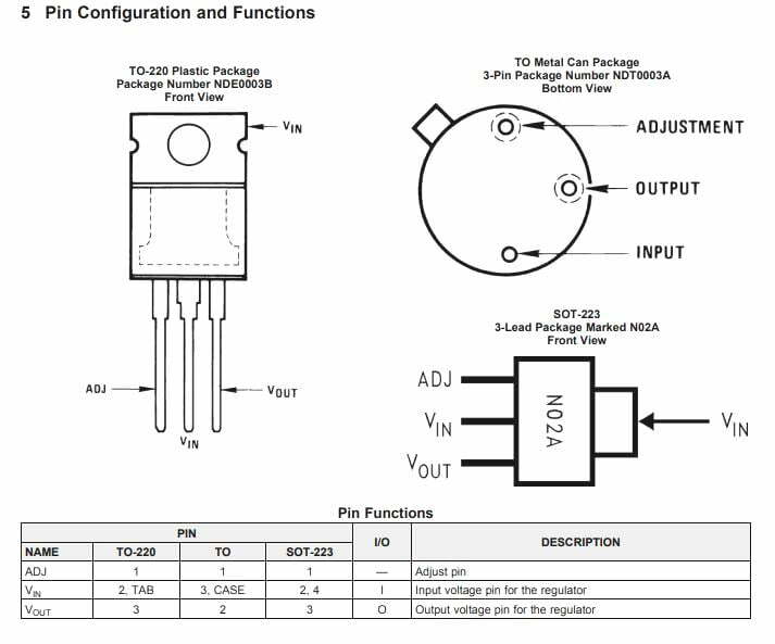
Pinout details and operation
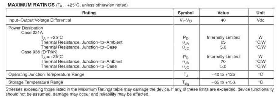
LM337 Absolute Maximum Ratings
LM337 Electrical Characteristics
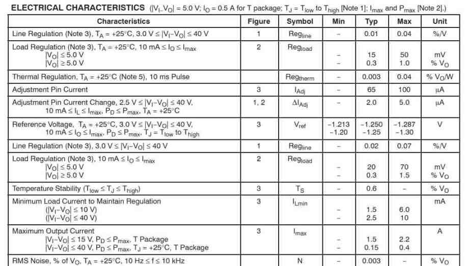
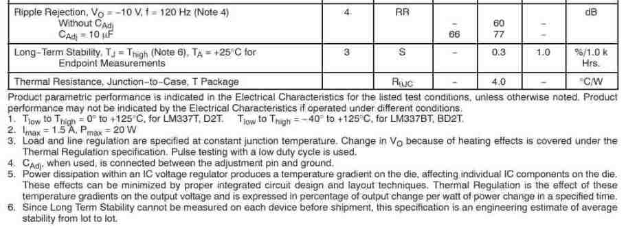
In the electrical characteristics for the listed test scenarios, product parametric performance is shown unless otherwise noted.
In a few cases, product performance may not be shown in the electrical characteristics as shown below.
Load and line regulation are recorded at constant junction temperature. V may vary due to heating effects as described in the thermal regulation specification. A low duty cycle pulse test is used here.
After C ADJUST, if applied, connect between the ADJUST pin and ground.
If there is power dissipation inside an IC regulator, a temperature profile will be created on the chip. This will affect the individual IC components on the chip, and its effects can be mitigated by good circuit design and layout practices. The effects of these temperature profiles on the output voltage are given under thermal regulation, which is the percentage change in output per watt of power change over a specified interval.
Since it is not possible to quantify the long-term stability of each component prior to shipment, this specification is intended as a rough estimate of average stability.
Basic Circuit Operation and Working
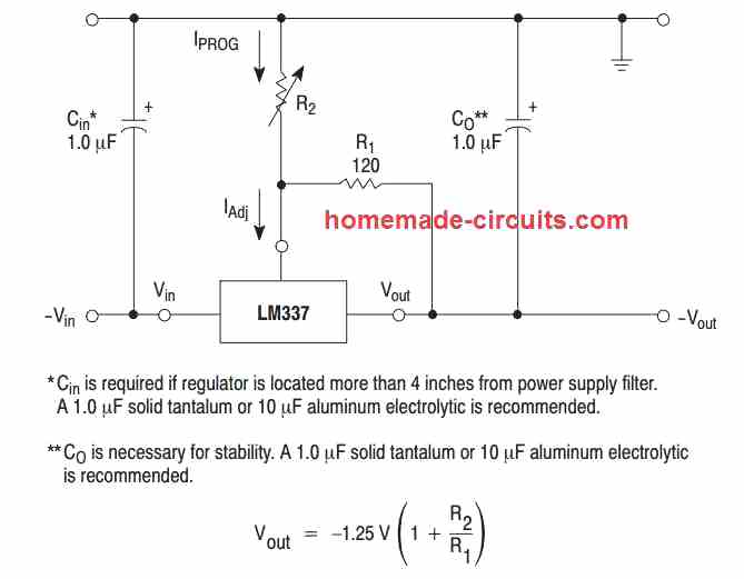
The LM337 is a floating voltage regulator with three terminals. It basically works by generating a precise -1.25 V reference voltage (Vref) between its output and the regulation terminal.
This reference voltage is converted to a programming current (IProcedure) created by R as shown in Figure 17. As a result, this constant current propagates from ground through R2.
The following formula describes the regulated output voltage:
Vout = Vref (1 + R2/R1) + Iadjusted R2
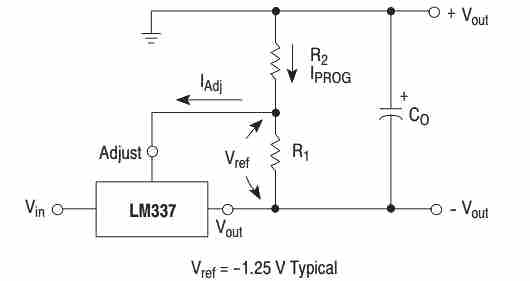
The LM337 can be used to adjust the adjust terminal (IAdjust) to less than 100 μA and keep it constant because the current flowing into IAdjust is
represents the error term in the above equation. To achieve this, all idle state operating current is sent back to the output terminals.
This requires a minimum load current. Once the load current falls below this minimum, the output voltage increases.
Also, since the LM337 operates like a floating regulator, the most important characteristic to perform at is the voltage difference across the circuit. Also, operating at high voltages relative to ground is important.
Load Regulation
The IC LM337 is very versatile and provides excellent load regulation provided certain precautions are ensured to obtain optimum performance.
One example is that the programming resistor (R1) must be placed as close to the regulator chip as possible to reduce the line voltage drop, which can easily be in series with the reference potential and seriously affect the regulation efficiency.
The ground terminal of R2 can be returned close to the load ground to achieve remote ground sensing and enhance load regulation.
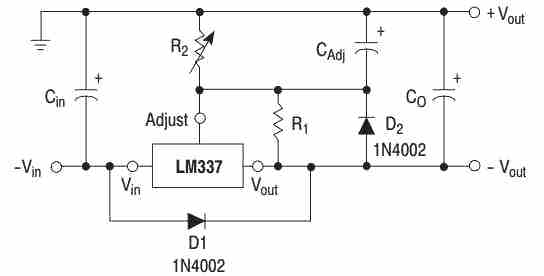
External capacitor
We recommend using a 1.0 μF tantalum input bypass capacitor (CIN) to minimize sensitivity to input line impedance.
You can bypass the adjust terminal to ground to enhance ripple rejection. This capacitor (Cadjust) limits the ripple when the output voltage is adjusted to a higher level.
Using a 10 μF capacitor improves ripple rejection by approximately 120 dB at 15 Hz when using a 10 V application.
The output capacitance (CO) is provided by a tantalum or 10 μF aluminum electrolytic capacitor to ensure stability.
It is also necessary to select any one of them to have an ESR (equivalent series resistance) value that does not decrease.
Low ESR or low ESR rated capacitors and ceramic capacitors may cause instability or permanent oscillation in the application.
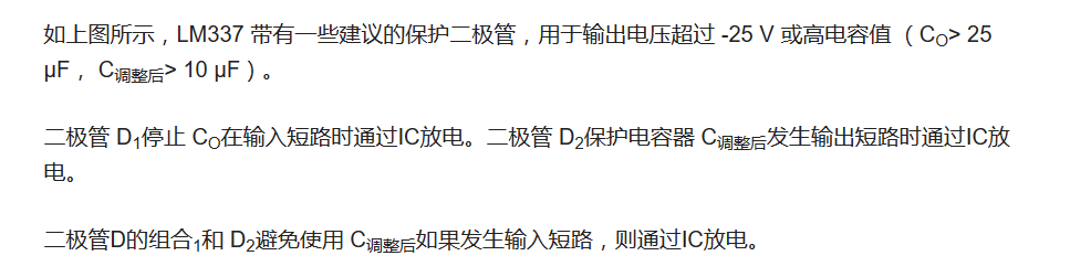
Protection diode
If you use external capacitors with any voltage regulator IC, you may want to seriously consider including protection diodes to avoid discharging the capacitors through low current points into the regulator.
- LM337 pin diagram and parameters, LM337 application circuit diagram
- Why do we need a MOSFET gate resistor? MOSFET Gate Resistor Placement
- How do Zener diodes protect circuits?
- What is the difference between CPLD and FPGA?
- What is a D flip-flop and how does it work?
- What is power factor and three ways to improve it
- DIY a decorative lamp
- Basic characteristics/working principles and application circuits of tunnel diodes
- Simple LED advertising light circuit
- LED Bicycle Lights
- Energy-saving motorcycle rectifier regulator circuit diagram
- High-precision voltage regulator using KTA431 (TL431)
- 6 to 9V 100mA voltage regulator circuit
- Current reduction protection voltage regulator circuit
- 5V power regulator circuit with symmetrical output
- Automatic voltage regulator schematic diagram
- Tube AC electronic voltage regulator circuit diagram
- Expansion type voltage regulator 1 circuit diagram
- Load line and control line separate voltage regulator circuit diagram
- Dual Channel Voltage Regulator Circuit


 京公网安备 11010802033920号