What is a D flip-flop and how does it work?
Source: InternetPublisher:fish001 Keywords: latch D flip-flop flip-flop Updated: 2025/01/10
What is a trigger?
Latches and flip-flops are sometimes grouped together because they can both store a single bit (1 or 0) at their output. In contrast to latches, flip-flops are synchronous circuits that require a clock signal (Clk). D flip-flops are only active when the clock is on.
0 to 1 (rising edge) or 1 to 0 (falling edge) stores the new value from the D input.
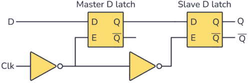
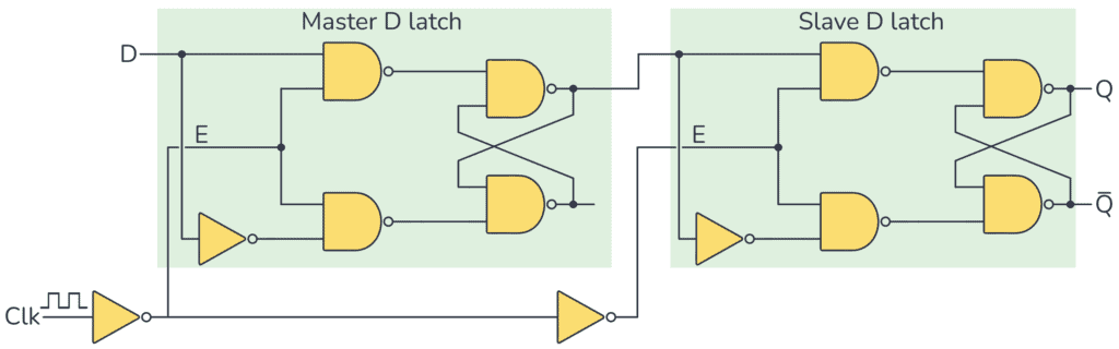
A D flip-flop is made of two D latches. You can see a D flip-flop that is updated on a rising edge below:
 D flip-flop master-slave circuit
The timing diagram for this circuit is shown below. It shows the behavior of a rising edge triggered D flip-flop. The output Q changes to the value of the D input only when the clock changes from 0 to 1.
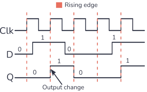
Timing diagram of D flip-flop
How does a D flip-flop work?
Since the output Q only changes when the clock input changes from 0 to 1, you get the following truth table:
Clock DQ Description
0XQ Memory
(No change)
0→1 (↑) 00 Reset Q to 0
0→1 (↑) 11 Set Q to 1
1XQ Memory
(No change)
In the first and last rows of the truth table, the clock inputs are 0 and
1. Neither of them is a rising edge signal, so nothing will happen. The Q output retains whatever value it has. In this case, no matter what value the D input has, the Q output will not change, it will hold its value unchanged. This is how this circuit "remembers" a point.
Look at the middle two rows. The clock input here goes from 0 to 1, so you have a rising edge. That means if the D input is 0, the Q output will reset to 0. If the D input is 1, the Q output will be set to
1.
Presets
The D flip-flops you find in ready-to-use chips (such as the CD4013) also usually have set and reset inputs that you can use to force the D flip-flop to either a 1 or a 0 on the output.
Using these pins is sometimes called "presetting" the D flip-flop.
Advantages of D Flip-Flop vs Latch
D Latch Circuit
One of the disadvantages of a D latch is that its output can change at any time when its enable pin is 1. Therefore, if a clock signal is applied to a D latch, Q
The output may also change.
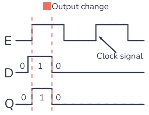
In the timing diagram above, you can see that within one clock cycle, the output is both a 1 and a 0 because the D input changes during the clock pulse. This is something you don't want to happen in a clocked digital system.
To make this flip-flop change its output only on the rising edge of the clock signal, you can build a master-slave D flip-flop circuit, which requires a combination of two D latches, as shown below:
D How Flip-Flops Work
When the Clk input is 0, the output of the master latch will change to the output of the D input.
If Clk is 0, it means the enable input of the slave latch is also 0. So nothing happens to the output of this latch.
But at the moment when Clk changes from 0 to 1 (rising edge), the enable input of the slave latch is set to 1. This means that when Clk changes from 0 to 1, whatever is at the output of the master latch will be saved to the output of the slave latch.
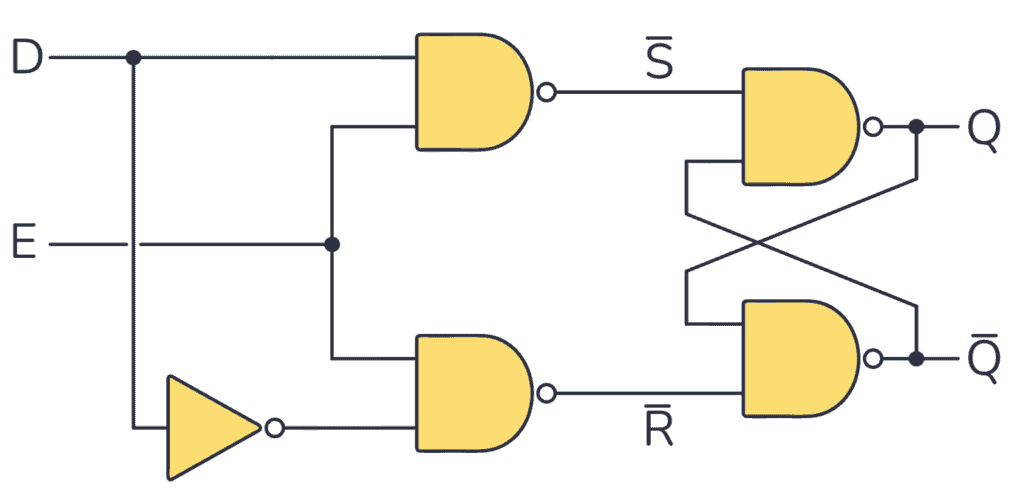
If you replace the symbol with a D latch built with NAND gates, you get:
- This article will tell you the hard requirements of operational amplifiers
- Analysis of the basic principle of measuring resistance by bridge method
- Analysis of the working principle of CMOS/CCD image sensor
- Why Do Amplifier Fuses Blow? How Do You Prevent Amplifier Fuses from Blowing?
- How do you calculate the value of capacitors in series? Why use capacitors in series?
- How to Build a Simple Temperature Indicator Circuit Using NTC and PTC Thermistors
- What is the difference between JFET and MOSFET
- Summary of knowledge points of multiplexer
- What is the difference between high-side and low-side resistive current sensing
- An example of proportional integral circuit diagram
- single-ended input flip-flop
- Typical circuit of integrated D flip-flop
- Circuit structure of RS flip-flop
- Bistable flip-flop practical circuit d
- Interface circuit between thyristor and MFC8070 zero-voltage integrated trigger
- Humidity control circuit using D flip-flop and operational amplifier
- Flip-flop circuit
- Electronic code lock circuit with trigger
- Astable flip-flop with starter
- high speed trigger


 京公网安备 11010802033920号