How to make a simple 0-5V voltmeter using 8051 microcontroller
Source: InternetPublisher:D先生 Keywords: Microcontroller voltmeter Updated: 2025/02/11
In this project, a simple 0-5V voltmeter is made using 8051 microcontroller. The sensitivity of this digital voltmeter is 200mV which is a bit low but this project is intended to demonstrate how to interface an ADC and a seven segment display to an 8051 microcontroller to get a digital readout of the input voltage.
In this case, ADC0804 is the ADC and the microcontroller used is AT89S51. Before trying this case, learn how to connect ADC to 8051 microcontroller and how to connect seven segment display to 8051 microcontroller, which will give you a good understanding of the basics.
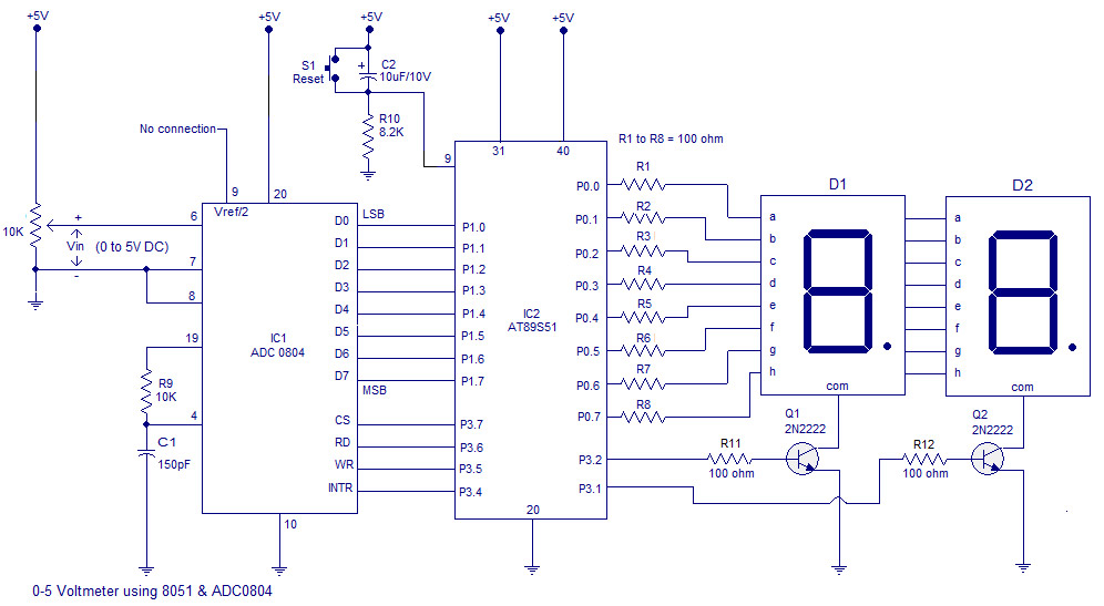
1. Digital voltmeter circuit diagram
In the circuit, Vref/2 (pin9) of ADC is kept open circuit, which means the input voltage span can be from o to 5V and the step size will be 5/255=19.6mV. The formula for the digital output of ADC0804 is Dout=Vin/step size. In this circuit, for an input voltage of 1V, the digital output will be 1/19.6mV=51, hence the binary equivalent of 51, i.e. 00110011. The digital output of ADC is connected to P1.0 of the microcontroller. The control signals of ADC, i.e. CS, RD, WR and INTR are taken from P3.7, P3.6, P3.5 and P3.4 pins of the microcontroller respectively. A 2-bit multiplexed seven segment display is connected to port 0 of the microcontroller. The control signals of the display driver transistors Q1 and Q2 are taken from P3.2 and P3.1 of the microcontroller. The push button switch is S1.
First, the program controls the ADC to produce a digital output corresponding to the input voltage. This digital output is scanned through P1.0 and loaded into the accumulator. The value in the accumulator is then divided by 10 to omit the last digit. For example, let the input voltage be 4V. Then the corresponding digital output of the ADC will be 204D (D stands for decimal). After dividing by 10, the value left in the accumulator is 20D. This 20D is then multiplied by 2D, resulting in 40D. The next goal of the program is to manipulate this 40D and make a 4.0 reading on the display. To do this, the 40D is divided by 10D again. This results in 4 inside the accumulator and 0 inside the B register. The program then uses a lookup table to get a digital drive pattern of 4, puts this pattern on port 0 and activates Q1. After a 1ms delay, 10000000B is loaded to P0, which is the dot. After another 1ms delay Q1 is deactivated, the content in B (i.e. 0) is moved to A, the correct digital drive pattern of 0 is obtained using the lookup table, this pattern is placed on port 0 and activates Q2. After another 1ms delay, Q2 is deactivated and the cycle repeats.
2. 8051 digital voltmeter program
ORG 00H
MOV P1,#11111111B
MOV P0,#00000000B
MOV P3,#00000000B
MOV DPTR,#LABEL
MAIN: CLR P3.7
SETB P3.6
CLR P3.5
SETB P3.5
WAIT: JB P3.4,WAIT
CLR P3.7
CLR P3.6
MOV A,P1
MOV B,#10D
DIV AB
MOV B,#2D
MUL AB
MOV B,#10D
DIV AB
SETB P3.2
ACALL DISPLAY
MOV P0,A
ACALL DELAY
MOV P0,#10000000B
ACALL DELAY
MOV A,B
CLR P3.2
SETB P3.1
ACALL DISPLAY
MOV P0,A
ACALL DELAY
CLR P3.1
SJMP MAIN
DELAY: MOV R3,#02H
DEL1: MOV R2,#0FAH
DEL2: DJNZ R2,DEL2
DJNZ R3,DEL1
RET
DISPLAY: MOVC A,@A+DPTR
RET
LABEL: DB 3FH
DB06H
DB5BH
DB4FH
DB 66H
DB 6DH
DB 7DH
DB07H
DB 7FH
DB 6FH
- Make an alcohol tester based on 8051 microcontroller
- Introduction to the use of UnoArduSim
- Make an Interactive Arcade Bedside Clock
- Interface circuit between AD574A and single chip microcomputer
- Using PIC microcontroller to make a temperature and humidity meter
- Digital frequency meter made with ATmega8 microcontroller
- FPGA and DAC0832 interface circuit
- Make a capacitive soil moisture sensor using ESP32
- Experiment on using 51 microcontroller to drive relay
- Use printer port to make programmable frequency generator circuit
- Design of temperature detection circuit implemented by single chip microcomputer
- Negative voltage generation circuit diagram
- PCF8591 hardware interface (circuit diagram pin diagram)
- Two types of negative voltage generation circuit diagrams of single-chip microcomputer
- Anti-interference circuit
- Automatic voltmeter circuit with impedance converter
- Multi-range voltmeter circuit using 0 to 1mA meter
- Multi-channel DA and microcontroller optical and electrical interface circuit
- Keyboard circuit composed of 8031 microcontroller P1P2 port
- Microcontroller universal digital tachometer circuit


 京公网安备 11010802033920号