How to use 8051 microcontroller to control stepper motor?
Source: InternetPublisher:柯南道尔 Keywords: MCU Stepper Motor 8051 MCU Updated: 2025/02/11
In this article, we have explained how to control stepper motors using 8051 microcontroller. Stepper motors are widely used in industrial, medical, and consumer electronics applications. In short, it is used anywhere that an object needs to be rotated or positioned accurately.
1. What is a stepper motor?
A stepper motor is a brushless motor that converts electrical pulses into mechanical rotations. As the name suggests, it rotates in steps according to the input pulses. A stepper motor usually has multiple field coils (phases) and a toothed rotor. The step length of the motor is determined by the number of phases and teeth on the rotor. The step length is the angular displacement of the rotor in one step. If the stepper motor has 4 phases and 50 teeth, it will take 50×4=200 steps to make a full rotation. So the step angle will be 360/200=1.8°.
The stepper motor we use has 4 poles and a 1/64 reduction gear mechanism to increase torque. The step angle of the motor is 5.64°. But when the reducer is taken into account, the step angle of the output shaft is 5.64/64°. The internal schematic diagram of the stepper motor is as follows:

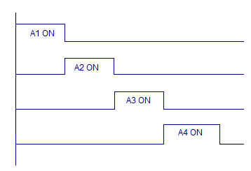
A stepper motor rotates by turning on each phase one by one for a given time. The sequence is shown in the following figure:
2. Schematic diagram
The circuit diagram for connecting the stepper motor to 8051 is shown above. The P1.0, P1.1, P1.2, P1.3 pins are used to control the A1, A2, A3, A4 phases of the stepper motor respectively. ULN2003 is used to drive the individual phases of the stepper motor. ULN2003 is a Darlington transistor array used to drive high current loads such as relays and motors. ULN2003 has 8 independent channels, each with a capacity of 1A. Channels can be connected in parallel to increase the current capacity. Each channel is equipped with an independent freewheeling diode. ULN2003 works in current sinking mode. Each channel is activated by providing a logic low level at the corresponding input. For example, if we set pin 1 of ULN2003 to low, the A1 phase of the stepper motor is turned on.
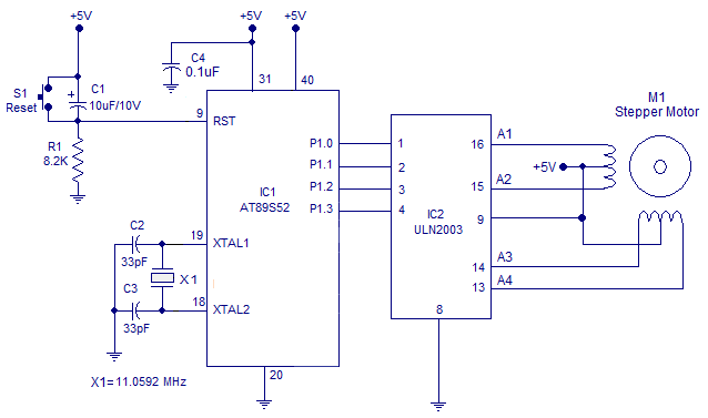
The program starts by clearing P1.0 to activate phase 1 (A1) of the stepper motor. This condition is maintained for 65 milliseconds and then P1.0 is set to deactivate phase 1 of the motor. The same process is then repeated for port pins P1.1 to P1.3 and the entire loop repeats over and over again, causing the motor to rotate clockwise.
The microcontroller's Timer 0 is configured in Mode 1 to generate a 65 millisecond delay, which is the width of each control pulse.
3. Program Code
A1 EQU P1.0
A2 EQU P1.1
A3 EQU P1.2
A4 EQU P1.3
ORG 00H
MOV TMOD,#00000001B
MAIN:
CLR A1
ACALL DELAY
SETB A1
CLR A2
ACALL DELAY
SETB A2
CLR A3
ACALL DELAY
SETB A3
CLR A4
ACALL DELAY
SETB A4
SJMP MAIN

DELAY:MOV R6,#1D
BACK: MOV TH0,#00000000B
      MOV TL0,#00000000B
      SETB TR0
HERE2: JNB TF0,HERE2
      CLR TR0
      CLR TF0
      DJNZ R6,BACK
      RIGHT
- Are more bits in an MCU better?
- Working principle of DCC module, practical application and precautions of DCC module
- Hardware interface circuit between CH375 and single chip microcomputer
- How to design an AirPlay speaker using Raspberry Pi Zero
- How to use ADXL335 to realize the design of gesture control robot
- 815ept motherboard
- Minimum system circuit of XC4003
- a watchdog circuit
- Usb mouse circuit diagram
- Circuit diagram: 8515 extended RAM
- Microcontroller buzzer control program and drive circuit diagram
- CNC machine tool and computer communication circuit diagram design
- Dual audio decoding electronic circuit
- Negative voltage generation circuit diagram
- Signal input circuit a
- Use MC34063 as a 12-volt programming power supply for single-chip microcomputer
- Optoelectronic interface circuit between single-channel DA chip DAC0832 and microcontroller
- Bicycle measuring meter circuit using EPSON microcontroller
- Method of two-way serial communication between PC and 8031 microcontroller
- Reactive stepper motor PWM speed regulation circuit


 京公网安备 11010802033920号