How to use a microcontroller to control a servo motor?
Source: InternetPublisher:睡不醒的小壮 Keywords: Microcontroller servo motor Updated: 2025/02/07
The servo motor is a commonly used motor. In this article, we will learn how to use a microcontroller to control the servo motor. The case uses the PIC16F877A microcontroller as an interface connection and control example.
What is a servo motor?
A servo motor is a special motor that runs according to given instructions. It provides precise angular control, which means that unlike other motors that rotate as soon as power is applied, the servo motor only rotates to a certain extent or until the next rotation is required, before which the motor will stop and wait for the next instruction to perform further actions. Therefore, the servo motor needs to be controlled by the servo circuit to rotate as required, and its angular rotation and final movement are determined by the position feedback, and the input of its control line also determines the required position of the output shaft.
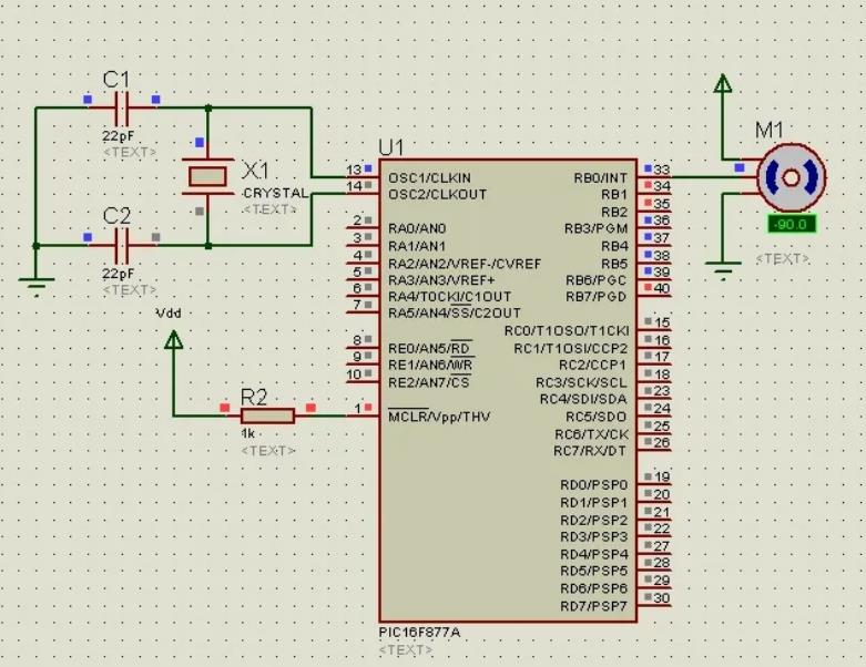
Servo motor circuit diagram of servo motor and PIC16F877A interface:

It has a very simple circuit diagram. The control wires of the servo motor are directly connected to the RB0 pin of the microcontroller. This pin will provide the required angular displacement of the motor. In this project, let's assume that we are using a servo motor whose angular rotation is limited to 0°-180°. We can control the rotation of the motor with maximum accuracy to achieve the desired angle by using pulses of varying width.
A pulse is provided to the servo motor after every 20 milliseconds (20000 microseconds). The angular position of the motor is determined by the length of this pulse. Angular positions 0°, 90°, and 180° are demonstrated in the code.
Below is the C code for PIC microcontroller interface to control the servo motor. We write the following servo motor code to interface with PIC in the compiler:
void Rotation0() //0 degrees
{
unsigned int i;
for(i=0;i<50;i++)
{
PORTB.F0 = 1;
Delay_us(800); //800us pulse
PORTB.F0 = 0;
Delay_us(19200);
}
}
void Rotation90() //90 degrees
{
unsigned int i;
for(i=0;i<50;i++)
{
PORTB.F0 = 1;
Delay_us(1500); //1500us pulse
PORTB.F0 = 0;
Delay_us(18500);
}
}
void Rotation180() //180 degrees
{
unsigned int i;
for(i=0;i<50;i++)
{
PORTB.F0 = 1;
Delay_us(2200); //2200us pulse
PORTB.F0 = 0;
Delay_us(17800);
}
}
void main()
{
TRISB = 0; // PORTB is used as output port
do
{
Rotation0(); //0 degrees
Delay_ms(2000);
Rotation90(); //90 degrees
Delay_ms(2000);
Rotation180(); //180 degrees
}while(1);
}
The individual functions for the motor angle rotation of 0°, 90° and 180° have been declared at the beginning of the code. In this tutorial, we have not used the actual pulse width modulation feature of the PIC16F877A to generate the pulses. Instead, the pulses are generated with the help of programmed delays. The delay duration for a particular angle is equal to the pulse length required to rotate the motor to the corresponding angle. That is, for an angle of 0°, the pulse width is about 800ms, so a delay of 800ms is introduced when the PORT pin RB0 is set high. Similarly, a pulse of 1500ms is required for a rotation of 90° and 2200ms for an angle of 180°.
In the main program, PORTB is set as an output port and all three functions are called with a 2000ms delay between them. This program rotates the motor in a certain pattern, say 0° – 90° – 180° – 0°, etc. This will continue to run in an infinite looping “do-while” loop until the program is aborted.
- Car ice warning circuit sharing
- Homemade Bluetooth controlled car using HC-05 Bluetooth module to communicate with mobile phone
- A small improvement to the temperature and water level indicator alarm
- DC motor drive circuit composed of L293D
- Motor self-starting circuit
- Design and analysis of a four-bit remote control component capable of remote reset
- Audio interface protection circuit
- Design and production of no-load automatic power-off device for household power supply
- Magnetic door and window anti-theft alarm
- Vibration anti-theft alarm circuit
- Negative voltage generation circuit diagram
- Two types of negative voltage generation circuit diagrams of single-chip microcomputer
- Interface circuit design of SPCE061A microcontroller and fingerprint identification module
- Special ultrasonic collision avoidance warning design for reversing
- Rural fish farming control circuit
- Egg heating control circuit
- Simple timing control circuit
- Mobile phone camera flash control circuit
- time control circuit
- Interface between LCD 7-segment display and microcontroller


 京公网安备 11010802033920号