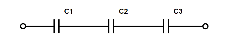
How do you calculate the value of capacitors in series? Why use capacitors in series?
Source: InternetPublisher:smallembedded Keywords: series capacitor capacitance Updated: 2025/01/10
Capacitors in series are capacitors connected in series. The result is always a capacitance lower than the lowest value.
In this guide, you'll learn why this is so and how to calculate their combined value. I'll also present a simple rule of thumb that you can use when you don't have a calculator handy.
Why do you get lower values?
When you connect capacitors in series, you connect them one after the other. You can think of them as a capacitor where one value is always lower than the lowest value.
For example, if three 300 μFs are connected in series, the combined capacitance becomes 100 μF. This is useful for obtaining specific capacitor values that are not currently available in the component selection.
The fact that capacitance gets lower as you add more capacitors may sound counterintuitive at first.
But when you think about how capacitors work, it starts to make sense: a capacitor is basically just two metal plates placed close to each other with an insulating material in between.
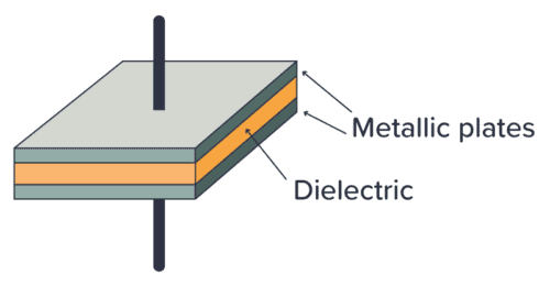
The more space between the plates, the lower the capacitance. So when you put two (or more) capacitors in series, you get more space between the first and last plates. And the capacitance gets lower and lower.
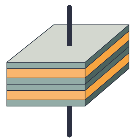 Two internal capacitors connected in series
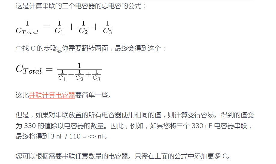
How to calculate the value of capacitors in series
Capacitors in series are calculated the same way as resistors in parallel.
Calculation Example
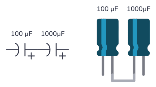
Suppose you have a 100 μF capacitor and a 1000 μF capacitor in series. What is the total capacitance of these two?
You can use the formula above and just enter the values as follows:
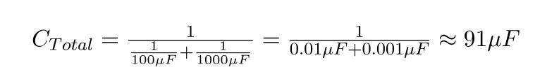
This means that the capacitance of the two capacitors in series is 91 μF.
Voltage across series capacitors
The voltage across capacitors connected in series will be divided between the individual capacitors. If you know that there is 5V across all the capacitors, that means the sum of the voltage across each capacitor will be 5V.
But it is difficult to say what the value of each capacitor is, because it depends on its capacitance, internal resistance and charge.
This is not specific to capacitors. Any series connection of components will divide the total voltage between the components. If you are not familiar with this concept, I recommend reading up on the basics of voltage and current.
Why use capacitors in series?
The most common reason for connecting capacitors in series among the hobby is simply that you don't have the exact capacitor value you need. By connecting multiple capacitors in series, other values can be achieved.
Let's say you built a blinking light circuit and discovered that the LED blinks too slowly. In the schematic below, you used 100μF for C1, which was the only value in the component kit.
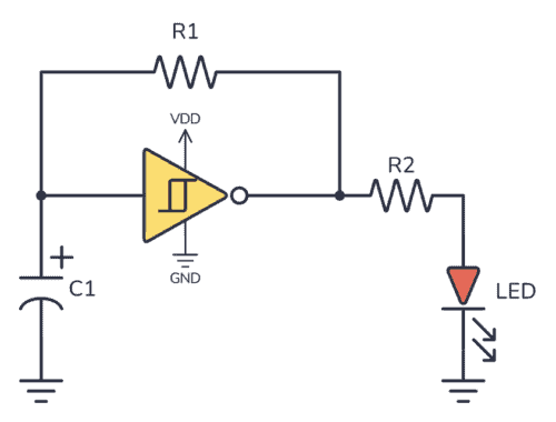
By adding another 1 μF in series with C100, the total resistance becomes 50 μF. Instead, your light flashes at twice the speed.
Generally you never need to put a capacitor in series unless you need to reach a capacitance value that you don't have on hand.
Summarize
The formula for calculating the value of capacitors in series becomes much easier if you use the same value for all capacitors. The result then becomes the value 1000 divided by the number of capacitors. For example, five 1000 μF capacitors in series
The capacitor becomes 5 μF / 200 = 《》 μF.
Typically, capacitors are placed in series only when a specific value is required that is not available.
- Voltage divider circuit calculation formula, where to find the voltage divider circuit?
- What is the function of a voltage regulator in a circuit? How to connect a voltage regulator?
- How do Zener diodes protect circuits?
- Which TVS diodes are suitable for RS232/RS485 and Controller Area Network applications?
- This article will tell you the hard requirements of operational amplifiers
- DIY a decorative lamp
- Build a musical fountain using Arduino and sound sensor
- Touch circuit design and analysis
- LED Bicycle Lights
- An example of proportional integral circuit diagram
- Capacitance measurement circuit c
- The structure and principle of AC induction motor
- LC filter circuit
- Current relay three-level starting circuit
- Capacitive impedance series negative feedback circuit
- Pure resistive series negative feedback circuit
- Circuit diagram of a diode connected in series across a potentiometer
- Circuit diagram of a diode connected in series across a potentiometer
- Series switching regulated power supply circuit diagram with output of 5V and 10A
- Series loss test circuit diagram


 京公网安备 11010802033920号