Voltage divider circuit calculation formula, where to find the voltage divider circuit?
Source: InternetPublisher:念念Brown Keywords: Resistors voltage divider circuits Updated: 2025/02/07
The so-called voltage divider circuit refers to a circuit that divides the voltage between two resistors. We often see it in some simple and advanced circuits. In this article, the teacher will introduce its working principle and calculation method.
1. Voltage divider circuit calculation formula
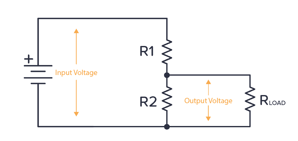
What does a voltage divider circuit look like? As shown in the figure below, when you connect two resistors like this, we can calculate the output voltage on both sides:
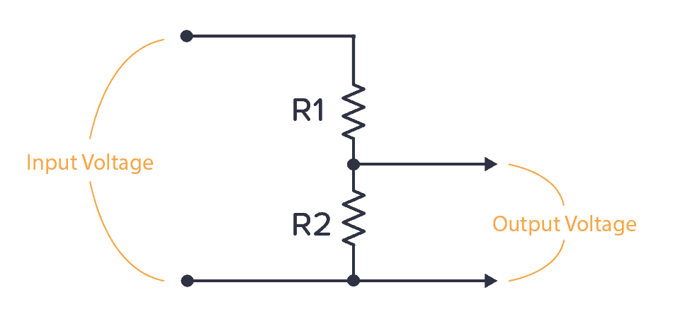
The formula for calculating the output voltage is:

2. Where to find the voltage divider circuit?
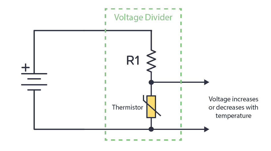
A classic example of a voltage divider circuit is for analog sensors. For example, a thermistor is a temperature sensor. It changes its resistance depending on the temperature. If we connect it with a known resistance value in a voltage divider circuit, we can get a voltage that depends on the temperature:
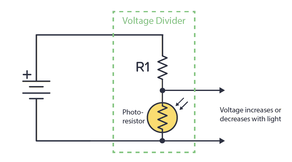
Alternatively, you can use a known resistor in conjunction with a photoresistor. A photoresistor changes resistance based on the amount of light it detects. This way, you have a circuit that increases or decreases voltage based on light.
We can connect the output of any of these circuits into a comparator to check if it is above or below a certain voltage. And then do something based on that. For example, if the temperature is above 40 degrees, turn on the fan.
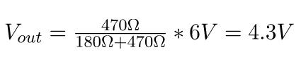
(1) Calculation example: different resistance values
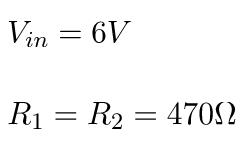
Assume we have the following values:
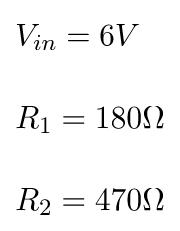
By using the formula above, we get:
(2) Calculation example: Equal resistance values
Now, assume that R1 and R2 have the same value.
By using the formula above, we get:
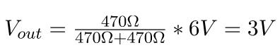
This means that when both resistors have the same value, the output is always half of the input.
3. Can a voltage divider circuit be used as a power supply?
For example, someone might ask, if there is a circuit that requires 4.5V, can a voltage divider circuit with two 500Ω resistors be used to get 4.5V from a 9V battery?
Unfortunately, it's not easy.
Because, any circuit you want to power has internal resistance. So from the perspective of the voltage divider, any circuit connected to the voltage output can be seen as a resistor in parallel with R2 (R LOAD ).
What would happen if the internal resistance of the circuit (R LOAD ) was also 500Ω?
Now, R2 in the voltage divider formula becomes R2 and R
The parallel resistor of LOAD. This is just 250Ω. If you put this into the voltage divider circuit formula, you will get an output voltage of 3V, not the 4.5V you want.
For power supplies, you want the voltage to remain at the chosen level, regardless of whether the connected circuit has high or low internal resistance. This is why voltage divider circuits are not often used in power supplies.
If you really want to use it, it would be better to use a voltage regulator.
- Does lithium iron phosphate battery need a protection board? The correct way to charge lithium iron phosphate battery
- Which one is better, NPN or PNP transistor?
- What is the relationship between capacitance and impedance in an AC circuit? How do you calculate the impedance of a capacitor?
- Capacitance detection circuit configuration, how to deal with low frequency and high frequency noise?
- What is the difference between CPLD and FPGA?
- Why Do Amplifier Fuses Blow? How Do You Prevent Amplifier Fuses from Blowing?
- How do you calculate the value of capacitors in series? Why use capacitors in series?
- DIY a decorative lamp
- Why use PWM? What are its advantages?
- Circuit diagram of a differential amplifier circuit
- Direct broadcast radio circuit
- Soil moisture indicator circuit
- Emitter coupled differential amplifier circuit
- Single tube DC coupled amplifier circuit
- Common emitter amplifier circuit b
- Series voltage stabilizing circuit with amplification link
- Roadblock flashing warning light circuit (2)
- Switching constant current source using integrated voltage regulator
- One-half voltage divider circuit diagram
- Analog voltage divider circuit for wideband X input


 京公网安备 11010802033920号