How to Make a Simple 2-Step Arduino Programmable Timer Circuit
Source: InternetPublisher:红水杯 Keywords: Timer Circuit Arduino Updated: 2025/01/03
In this article, we will learn how to make a simple 2-step Arduino programmable timer circuit that can be used to control the timer by independently adjustable ON and OFF
Timing to switch the electrical load on/off.
For example, if you want the light to stay ON for 24 hours and OFF for 2
You can do this by quickly modifying the program code. Likewise, you can customize the output timing to any other desired set of time intervals by changing the code appropriately.
void setup(){pinMode(13, OUTPUT);
}void loop(){digitalWrite(13, HIGH);delay(86400000);digitalWrite(13, LOW);delay(3600000);
}
You just need to compile the following code and upload it to your Arduino board and then start the timer function according to your specific application needs.
In the sample code above, the lines delay(86400000); and delay(3600000); determine the output ON and OFF delay time intervals, respectively, in milliseconds. Here, the numbers
86400000 milliseconds corresponds to 24 hours, while 3600000 represents a 1-hour delay.
You can customize these two values to achieve the desired output delay based on your personal preference.
Once set up and powered up, the Arduino will continue to switch between the two-step ON/OFF timing sequence as long as the system remains powered.
Circuit Diagram
The complete circuit diagram along with the Arduino connections can be seen in the image below:
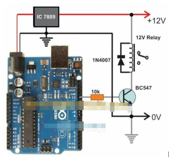
Arduino Single Pulse Timer Circuit
If you don't want the timer to loop through the two-step timer, but instead want the timer to be a one-shot type, which will go off permanently after a set delay, you can apply the following code:
int led = 13; // Pin 13 has an LED connected on most Arduino boards. unsigned long DELAY_TIME = 10000; // 10 secunsigned long delayStart = 0; // the time the delay startedbool delayRunning = false; // true if still waiting for delay to finishvoid setup() { pinMode(led, OUTPUT); // initialize the digital pin as an output.
  digitalWrite(led, HIGH); // turn led on

  // start delay
  delayStart = millis();
  delayRunning = true;
}void loop() { // check if delay has timed out
  if (delayRunning && ((millis() - delayStart) >= DELAY_TIME)) {
    delayRunning = false; // finished delay -- single shot, once onlydigitalWrite(led, LOW); // turn led off
  }
}
Parts Needed for the Arduino Programmable Timer Circuit
Arduino UNO Board = 1
IC 7809 = 1
BC547 = 1
1N4007 diode = 1
10K 1/4 W resistor = 1
Relay 12V/400 Ohm/SPDT/5A = 1
12V AC to DC adapter = 1
- The meaning and importance of circuit protection, common types of circuit protection
- Model rocket launch controller circuit
- How to build a simple tachometer using an infrared reflectance sensor
- A small improvement on the ordinary refrigerator motor starting circuit
- Manual automatic air compressor control circuit
- Simple phase failure protection circuit composed of intermediate relay
- Design and production of radio remote control fan stepless speed regulator
- Design and analysis of touch delay switch circuit composed of CD4011 and CD4001
- Simple three-phase motor phase loss protection circuit
- Simple disconnection burglar alarm
- One-digit display timer circuit diagram
- 1h timer circuit using LM122
- Make a timer circuit using a time clock
- Clever use of NE555 as long timer circuit diagram
- Sequential timer circuit diagram composed of 555 chip
- Timer circuit that can display remaining time
- Automatic exposure timer circuit
- Darkroom timer circuit
- Precision timer circuit diagram
- Simple and accurate timer circuit


 京公网安备 11010802033920号