Controlling LEDs with Node-RED in Raspberry Pi
Source: InternetPublisher:无人共我 Keywords: led raspberry pi Updated: 2024/12/27
Ever wondered if there is a way to prototype simple IoT solutions without spending days writing code or build practical advanced projects without coding. Yes, this is possible with the Node-Red platform. Developed by IBM, Node-RED is an open source programming tool for connecting hardware devices, APIs, and online services together in new and interesting ways. It provides a browser-based editor that can easily connect "flows" together using a variety of nodes in a palette, which can be deployed to its runtime with a single click.
It uses visual programming, allowing you to connect blocks of code (called nodes) together to perform tasks. In today's tutorial, we will look at how to deploy simple projects on the Raspberry Pi using Node-RED. The Raspberry Pi node-red tutorial will cover;
Install Node-RED on your Raspberry Pi.
Introduction to the Node-RED User Interface
How to set up a Node-RED flow
How to control Raspberry Pi GPIO pins using Node-RED
How to use Node-RED input, output and if-else, such as using switches to make decisions
Prerequisites
This tutorial will be based on the Raspbian Stretch operating system, and I assume that you are familiar with setting up a Raspberry Pi with it, and that you know how to connect to the Pi via SSH using terminal software such as putty.
To easily complete this tutorial, I recommend that you use a monitor connected to the Raspberry Pi or use a VNC viewer software.
Although Node-Red runs from a web browser and can be accessed on a PC connected to the Pi via the Pi's IP address, I believe a VNC/monitor experience will give you a better experience.
As a demonstration of how Node-Red works, we will program a Raspberry Pi using Node-RED to control an LED connected to its GPIO, and then modify the program to allow the LED to be controlled via a tactile button connected to the Pi's GPIO.
Required Components
The following components are required to build this project;
Raspberry Pi 3 with SD card preloaded with Raspbian Stretch
100 Ohm Resistor (1)
Light Emitting Diode (1)
Breadboard (1)
Male to female jumper wires
Tactile Buttons (1)
Install Node-RED on the Raspberry Pi
Although Node-Red comes pre-installed on Raspbian Stretch OS, we need to upgrade it to enjoy some of its latest features. Upgrading Node-Red will
Upgrade existing users to LTS 8.x or 10.x Node.js and the latest Node-RED
Migrate any existing globally installed node to the user ~/.node-red space so that it can be managed by the palette manager. It will not update any existing user installed node. This must be done manually by the user (see below).
You can choose to (re)install additional nodes that come pre-installed on the full Raspbian Pi image.
However, the process of upgrading Node-Red is similar to installing a new one, so for the purpose of this tutorial, we will treat it as a new installation so that people using other OS versions can follow along.
Follow the steps below to install/upgrade Node-RED on your Raspberry Pi.
We will first upgrade and update the pi to ensure everything on it is up to date and to avoid compatibility issues. Do this by opening a terminal or via ssh, then run;
sudo apt-get update
followed by
sudo apt-get upgrade
Once completed, run the following bash script on your terminal;
bash "(curl -sL https://raw.githubusercontent.com/node-red/raspbian-deb-package/master/resources/update-nodejs-and-NodeRed)
The bash script will do the following
Asks if you want to (re)install additional Pi nodes
Keeps a list of any globally installed node-red-nodes found in /usr/lib/node_modules
apt-get remove the existing Node-Red
Remove any node-red binaries from /usr/bin and /usr/local/bin
Remove any node-red modules from /usr/lib/node_modules and /usr/local/lib/node_modules
Detect if Node.js was installed from the Node.js package or Debian
If not v8 or newer - remove and install latest v8 or v10 LTS as appropriate (without using apt).
Clean the npm cache and .node-gyp cache to remove any previous versions of the code
Install the latest version of Node-RED
Reinstall any node that was previously installed globally under your user account
Reinstall additional Pi nodes if necessary
Rebuild All Node - Recompile any binaries to match the latest Node.js version
Add node-red-start, node-red-stop, and node-red-log commands to /usr/bin
Add menu shortcuts and icons
Add system scripts and set up users
If you add CPU temperature on Pi -> IoT example
The bash script above runs many commands as sudo and does remove the existing Node.js and core Node-RED directories. You can check the contents of the script on this GitHub page before running it to make sure it doesn't affect any projects you already have on your Pi.
Once the installation is complete, you should now see the Node-Red icon under the list of programming applications in the menu.
Start Node-RED on the Raspberry Pi
Node-Red can be started from the menu section of the Raspberry Pi desktop, from the terminal, or via ssh.
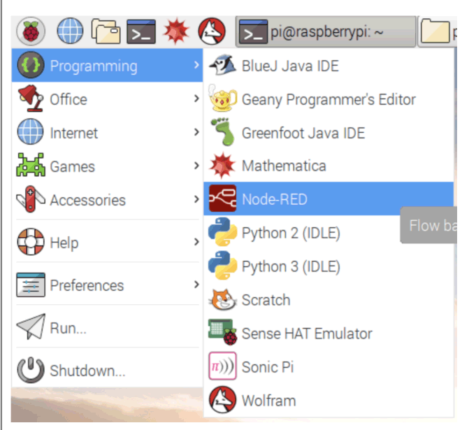
To start on the desktop of the raspberry pi, click on the Raspberry icon, hover over Programming and click Node-RED (Menu>Programming>NodeRed) to start it.
It can also be started via ssh or terminal;
Node Red Start
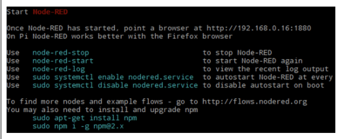
You should see a window similar to the image below showing Node-Red starting up on your desktop.
Once you see this, go to menu->internet and launch the chromium web browser. Although your Raspberry Pi does not require internet to run Node-Red, it uses a browser as its interface.
After starting chromium, type localhost:1880 in the address bar and press Enter. 1880 is the port on the Raspberry Pi that Node-Red is designed to communicate on. This should bring up the Node-Red interface, as shown below.
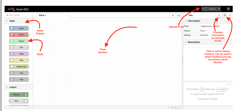
Understanding the Node-RED interface
The Node-Red interface includes the process panel, node panel, debug console, and information console, as shown in the figure above.
The Flow Panel is where you connect nodes together to create programs, called flows in Node-Red, while the Node Panel consists of objects that represent hardware, protocols, and software functionality associated with your device. It includes protocols like MQTT for IoT, and GPIO output and input modes for boards like the raspberry pi. The Information Console provides information about the highlighted/selected object, while the Debug Console works like an Arduino serial monitor to provide feedback while the flow is running. The Deploy button is used to upload the flow to the target hardware. The Menu button contains different upload types to help you get the most out of your project. With Node-Red up and running, we can now move on to building the demo project.
Schematic
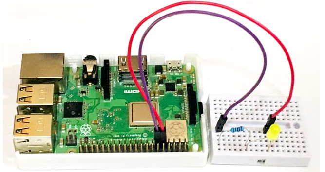
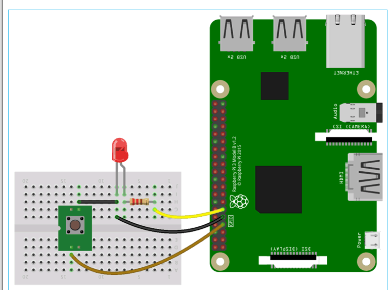
As mentioned in the introduction, our demo project today will control the GPIO of Raspberry Pi using Node-RED flows. To show the change of GPIO state, we connect an LED to the GPIO so that when a particular GPIO pin is turned on, the LED will light up and vice versa.
Connect the LED to the Raspberry PI as shown in the following figure.
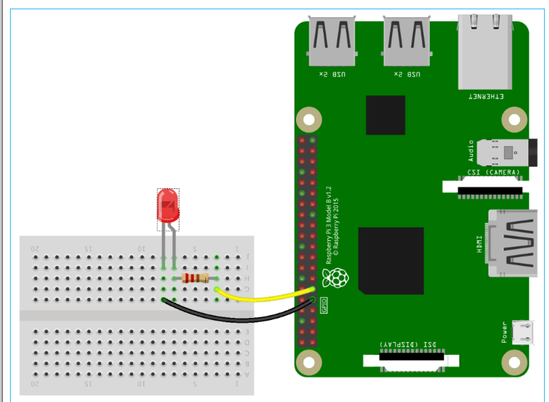
I also built the same thing on my hardware using a breadboard, LEDs, resistors, and some hookup wire. After making the connections, my hardware setup looked like this.
This project can be easily converted into a home automation project by just replacing the LED with a relay and any AC appliance, learn how to do this by going through various home automation projects.
Creating a flow in Node-RED
With the LED connected, we can move on to developing our flow. Programs in NodeRed are called flows, just like the Arduino IDE calls them sketches. Flows are created using a combination of nodes. You can create multiple flows that can run simultaneously, but in this tutorial, we will create a flow to turn an LED on/off.
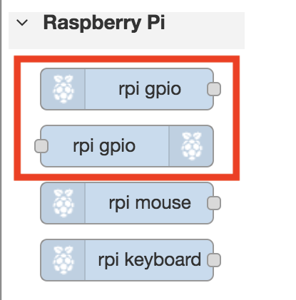
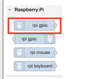
First, scroll to the bottom of the Nodes panel and you will see the raspberry pi node section near the end with two nodes labeled rpigpio. These nodes are used to communicate with the Raspberry Pi's GPIO. One of the nodes is for input, while the other is for output, distinguished by the position of the Raspberry Pi logo. For input nodes, the logo is before the text, while for output nodes, the logo is after the text, as shown in the image below.
In this tutorial we will be using an Output node, drag it to the Flow section of the interface. This step is similar to declaring a specific pin of the Arduino as an output using the pinMode() command. Double-click the Output node and a popup window will open as shown below, allowing you to edit the properties of the node.
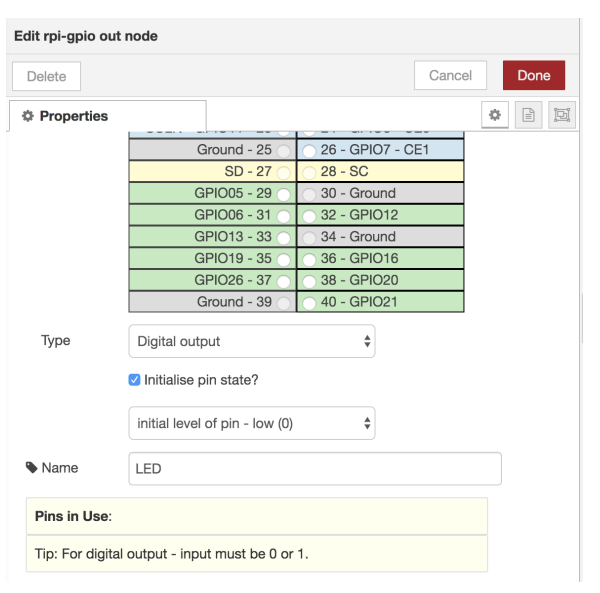
Under the pin property section, select GPIO17 (pin 11). Then set the type property to "Digital output" and check the "Initialize pin state?" checkbox. Leave the "Initial level of pin" option to Low (0). Give the node any name you like and click the Finish button.
The name of the node should automatically change to the name you entered under the property settings. For example, I named it LED, so the node name also changed to LED as shown below.

To turn the LED on/off, we need to use an input to drive the action. While we could use a button, I want to use this to introduce features in Node-RED that allow you to inject messages into a flow. These features are called inject nodes. We will use two inject nodes. One to turn the LED on, and another to turn it off.
Go to the Node Palette and drag an Inject Node into your flow. It is the first node in the palette with an arrow and the Inject Node is highlighted in the image below.
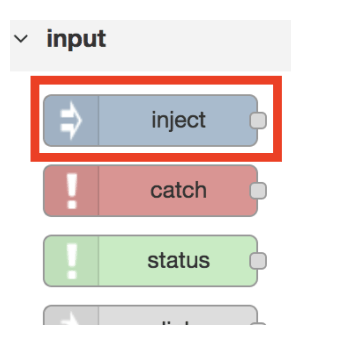
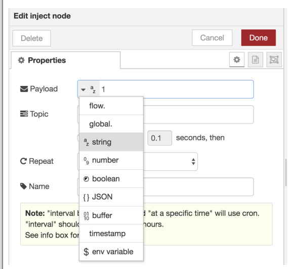
Double-click it to edit its properties. Change the data type to string by clicking the drop-down menu in front of Payload, and enter 1 in the Payload box. The value in the Payload box is the value that will be injected into the flow when the node is pressed. Set the node name to "ON" Press the "Done" button to save.
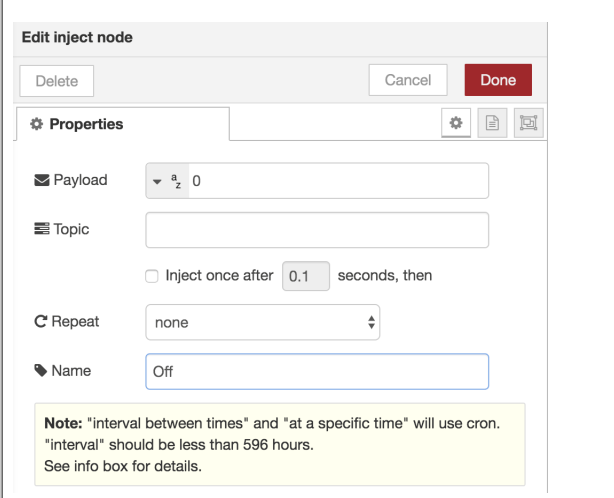
Repeat for the second node, setting the payload value to "0" and its name to "off" as shown below.
Under the Properties function, the Repeat drop-down menu can be used to automate the injection so that the button is pressed at intervals. This can be used to create a blinking effect. Connect the nodes together as shown below by dragging the grey dot on one of the nodes to another to create a flow.
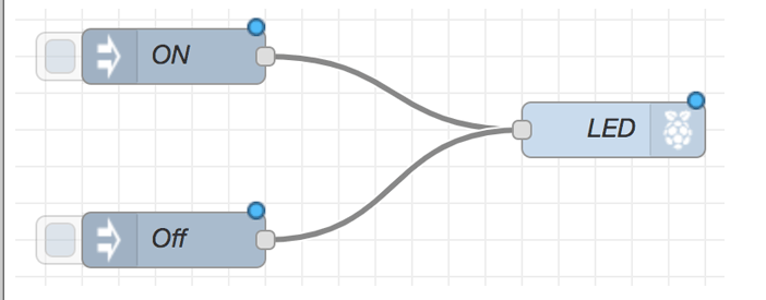
Once completed, we have now completed our first Node-Red Flow.
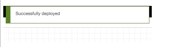
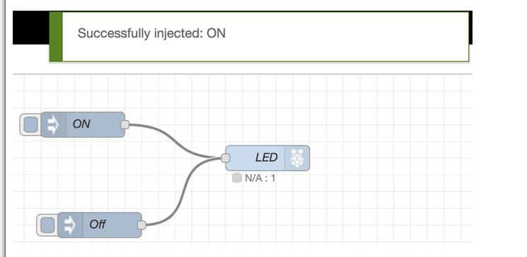
The next step is for us to deploy the process on the raspberry pi. Click the red deploy button. You should see "Successfully deployed" flashing at the top of the screen as shown below.
Click the gray button behind the Inject nodes to activate each node.

By clicking the Inject Node "on", you should see a successful injection "on" and the LED should light up. When you click the Inject Node "off", the LED should turn off.
That's it. The complete working of this setup can be found in the video linked at the bottom of this page.
Adding a button/switch to a Node-RED interface using a Raspberry Pi
To explain how to connect/add input elements to your flow, we will take the above flow a step further by adding a button to replace the inject node.
Connect the button to the Raspberry Pi so that one leg of the button is connected to ground and the other leg is connected to GPIO Pin 4 (Pin 11) of the Raspberry Pi as shown in the following figure.
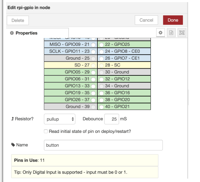
Once you have done this, go back to Node-Red and delete the two inject nodes we used previously, either by clicking on the node and pressing delete on your keyboard or by double clicking on the node and pressing delete in the popup. Once you have done this, scroll down the node palette to the raspberry pi section and select the input node. It is the one with the raspberry pi icon on the left, before the node name.
Drag the node into the flow and double-click it to edit the properties. Set the pin to GPIO 4 (pin 11) and set the pull-down in front of the resistor to pull-up. This will "pull up" GPIO 4 to a high level. Click the Done button when you have set the properties.
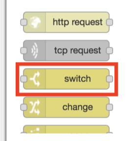
In order for us to make a logical decision when the switch is pressed, rather than just shorting GPIO4 to ground, we will use a switch node. Search for it under the Function section in the Node Palette and drag it into the flow.
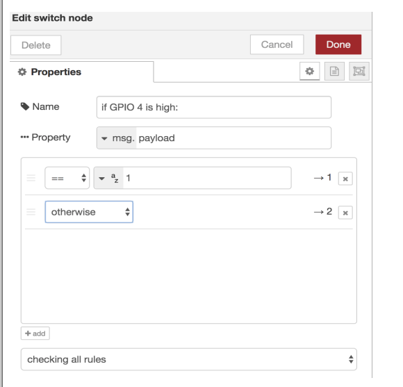
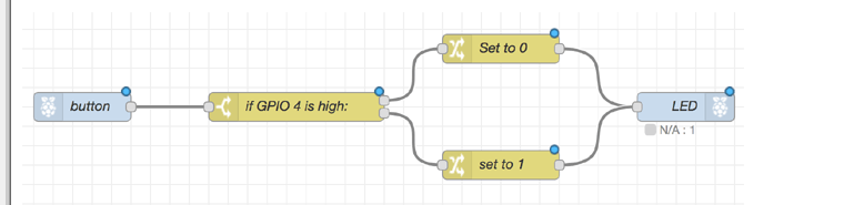
The Switch node allows you to make decisions in a similar way to an "if" statement. It can be set up to have different outputs depending on the value of an input. For this tutorial, we will configure it with two output paths, so that it should follow the first path when the msg.payload property is equal to 1 (the switch is not pressed), and will follow the second path if any other value other than 1 is observed at the input (the switch is pressed). Use the "+add" button to add a path. Double-click the node and configure it as described above. Click Done when you are finished.
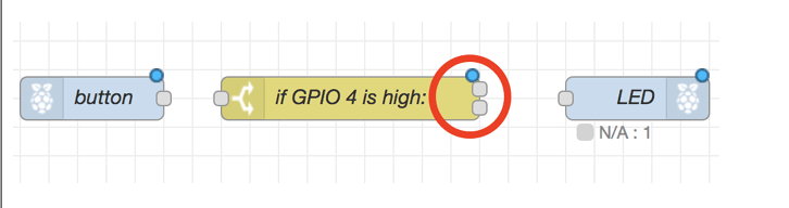
Once you click the Done button, you should see the two paths reflected in the appearance of the switch node, as it now has two connection points on the output side.
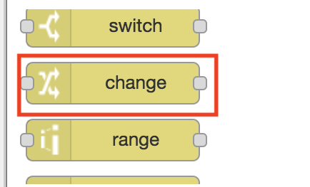
Next, we need to bring in a "Change" node. The Change node will be used to set the state of the LED based on the result of the Parameter node.
We will use two mutation nodes. The first will have its payload set to 0 as shown below, and the second will have its payload set to 1. Click Finish after editing the properties of both.
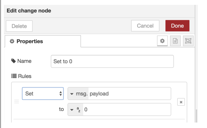
To explain it better, remember we used a pull-up resistor? So when the button is not pressed, the output of this pin will be HIGH (1), which means that if we pass it through the switch node, the LED will be "ON", since this should not be the case, we will use the "Change" node to set it to LOW (0). The second "Change" node is used to set the value to 1 so that when any other state other than a HIGH state is detected for GPIO pin 4, it should turn the LED "ON", since this means that the button has been pressed. Connect the Change node and the rest of the nodes together as shown in the following image.
Once completed we can now deploy the project. Check the connections to make sure everything is working correctly and then click the Deploy button. As usual, if successful you should see the Deployment Successful popup and can now control the LED using the switch.
While Node-Red allows you to easily and quickly build prototypes without having to worry about code, it may not actually be the best fit, especially for experienced developers who need flexibility and control over their programs. Still, it is a great tool that allows you to build prototypes in minutes.
- Servo motor pin diagram/working principle/application
- Car ice warning circuit sharing
- Build a Smart Garage Door Opener Using a Raspberry Pi
- How to Make a Simple Chicken Incubator
- Tutorial for building a remote-controlled Arduino Air-Boat
- How to Make a Hot Tub Smart and Remotely Operated with a Raspberry Pi
- What is a RADAX motor?
- One-way rotation circuit of motor controlled by contactor
- A novel and practical power line anti-theft and cutting alarm circuit
- Ultra-short wave item left behind reminder alarm
- Serial dynamic LED scanning circuit
- LED backlight driver module design circuit
- Three-phase phase loss alarm light circuit
- Five-digit LED level indication driver integrated circuit typical circuit
- CdS photoresistor as electronic photometric element circuit diagram
- LT3755 driver LED application circuit diagram
- Three-color marquee circuit diagram
- 5-point LED driver circuit diagram of HA7666P/TA7667P
- Fire emergency light circuit
- Light emitting diode (LED) display driver circuit


 京公网安备 11010802033920号