Designing a Simple Solar Voltage Regulator PCB
Source: InternetPublisher:公子李 Keywords: Voltage stabilizer solar charging Updated: 2024/12/10
In this article we will have a beginner project on how to design a solar regulator PCB. This solar charger is a very important circuit board that allows you to charge your solar energy to the maximum power output expected.
Components required for the project

Resistor 10K/1K × 1
Resistor 220 0603 Yageo × 1
Resistor 47k 1206 Stackpole Electronics × 1
10uF capacitor × 2
476CKR025M Illinois capacitor × 1
1N4007GP-E3/73 Vishay General Semiconductor × 1
Power socket × 1
Background
In modern technology, solar panels are charged by using Maximum Power Point Tracking (MPPT) technology. This is a technology that charges our solar panels by tracking the direction of the sun to ensure that the solar energy is concentrated at the point of maximum power output. Sometimes, this technology proves to be insufficient, especially when there is no sun, such as on cloudy and rainy days. Since we still need to use our solar energy, we have to charge them. Therefore, this solar charger will be of great significance in this case. The LT3652 is a DC to DC converter microcontroller that will help us provide the most efficient charging tracking for our solar cells. This will make the solar panels the most efficient and reliable in providing electricity to our homes.
Working Principle of LT3652
This happens to be the most efficient when compared to other charge regulators. It does DC to DC power regulation. First, they receive the DC input from the solar panel, convert it to a high frequency AC signal, and then finally convert it back to DC voltage and current according to the battery charging specifications. Input regulation is used to ensure that the panel remains at peak power output.
This type of converter can be configured to ensure that charging stops when the charge current drops below 1/10 of the programmed current.
Schematic diagram
The schematic below features the LT3652, a very critical component in the design. The converter will play the key role of stepping down, stepping up and changing DC to AC and back to DC to charge the solar cell.
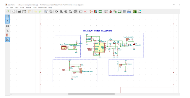
The barrel jack is our switch where we disconnect the battery inside the panel and connect the external battery which will charge the internal battery when the solar panel is not charging.
The following schematic was created using KiCAD EDA, a critical design tool.
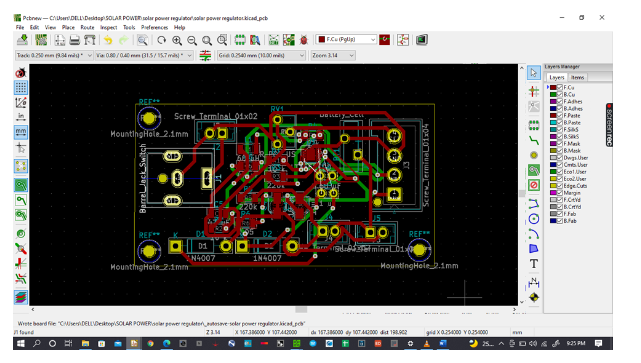
PCB Design
The above schematic file is converted into a PCB file.
During the design process, we can choose the size of the component or the size of the circuit board according to the design specifications or requirements.
We can also check the errors in the PCB with the help of the design check rules in KiCAD, which enables it to identify all the design errors. The solar charge controller is what charges our batteries and we should be very careful while making the connections to make sure we don’t miss any connection as any mistake can lead to the loss of our solar panels or our very expensive batteries.
The image below is a fully wired PCB board ready for layout.
After the layout and generation of the 3D view of our design, we got the following image.

Design and Manufacturing
Once the design is complete, I need to get it made. Now I have to communicate with a manufacturer who can help me with the manufacturing.
I use PCBWAY for my manufacturing. You visit Ordering - How do I submit an inquiry and place an order (pcbway.com) and ask for more information on how to order your PCBs to be manufactured.
You need to send all the manufacturing files generated by the EDA tool to the manufacturer. For me, I had to upload the Gerber files, BOM files, and Pick and Place files to make the process successful.
Bill of Materials
To solder the components that I use in my PCB, I need to order them for purchase. To do this perfectly, the Bill of Materials commonly known as BOM will play a key role. This can be generated from the same design tool that you use.
Generate this file from KiCAD;
Go to File then Manufacturing Output and select BOM File as shown below
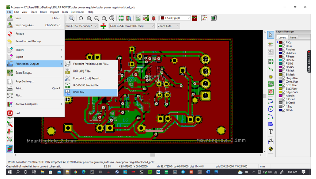
Click on it to generate an excel file save it. When you open the excel file this is what you get. You will need to edit it to match the manufacturer's requirements.

Gerber Files
To generate the Gerber files, go to Pot as shown below
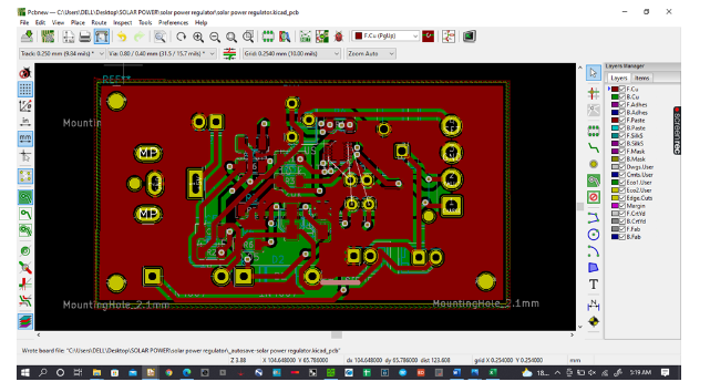
Click the icon to open the pop-up window below, then click
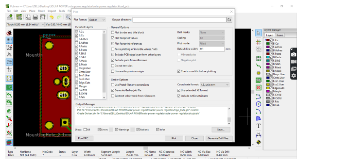
You will generate your Gerber files
This brings us to the end of this simple solar voltage regulator PCB design
- How to make a metal detector using the TDA0161 proximity switch chip?
- How to convert digital values into analog values by connecting MCP4725 with Arduino
- How to use Tesseract for optical character recognition on Raspberry Pi
- Build a Raspberry Pi-based QR code scanner
- The production of ultra-low-cost anti-theft system based on Blues wireless note card
- DIY an open source air quality monitor
- Automatic recovery electronic fuse with soft start function
- A simple memory reader/writer
- Simple and easy-to-make electronic mosquito repellent
- DIY Solar Detector
- Energy-saving motorcycle rectifier regulator circuit diagram
- Microprocessor power supply circuit diagram using linear voltage regulator
- Applications to change output voltage polarity (b)
- Battery Regulator Circuit for Solar System
- Current reduction protection voltage regulator circuit
- Low Power Supply Regulator ADM66304
- Expansion type voltage regulator 2 circuit diagram
- TL431 forms a series voltage regulator circuit
- LM2579 used as a step-down voltage regulator circuit diagram
- LM3578A used as a step-down voltage regulator circuit diagram


 京公网安备 11010802033920号