BA1404 transmitter with UPC1651 RF amplifier
Source: InternetPublisher:tBK9Ar Keywords: RF amplifier BA1404 transmitter Updated: 2026/03/20
BA1404 transmitter with UPC1651RF amplifier
The BA1404 transmitter includes an onboard RF amplifier to increase transmission range. Operating from 1-3V, the circuit comprises a monolithic integrated circuit of an FM stereo mixer, a 38kHz oscillator, an FM modulator, and a high-frequency amplifier. Due to numerous requests for detailed information about FM stereo transmitters on the "Electronic Newspaper" BBS, I have compiled information on simple discrete, combined, and integrated FM stereo transmitter experiments. The BA1404 combined with the μPC1651 is the easiest to build and debug, and offers very high frequency stability (compared to the previous BA1404 circuit). Transmit power is increased via the UPC1651 RF amplifier.
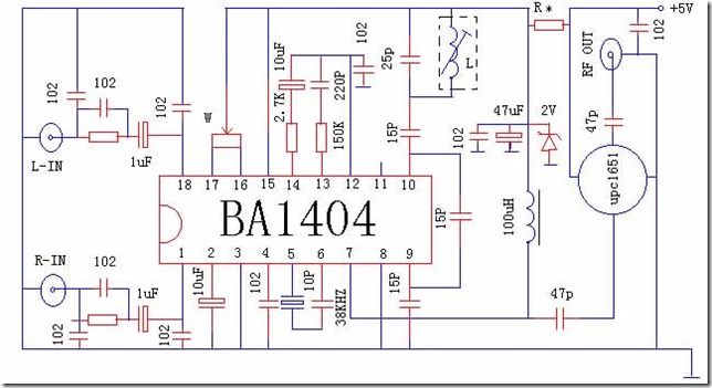
Working principle (see Figure I):
The stereo audio signal is enhanced by the input matching network consisting of pins 1 and 2, and then enters the mixer to generate a composite signal consisting of L+R and LR stereo sub-signals. The composite signal is amplified by outputting from pin 14 through a buffer (pins 16 and 17 are used to adjust the parameters of the composite signal, which can control the left and right balance).
The external discrete components and internal oscillator circuit at pins 4, 5, and 6 generate a 38kHz signal, which is supplied to the mixer and amplifier through a buffer. After passing through a 1/2 divider, the 38kHz signal is divided to obtain a 19kHz pilot signal, which is output from pin 13.
The composite signal and pilot signal output from pins 13-14 enter the FM modulator (the production sub-components at pins 9 and 10 determine the external oscillation frequency) through the matching network consisting of pin 11 to generate an FM signal, which is then amplified and output from pin 7.
Pin 2 is used for AF offset, pin 3 is used for AF grounding, pin 8 is the RF connection point, and pin 15 is used for positive power.
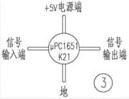
(Note: Reference voltage output pin 11 is for external discrete components to control the oscillation frequency, but it is not used here.) Pin 7 amplifies the output signal through μpc1651.
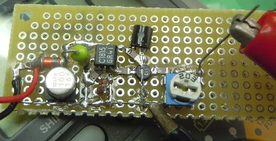
Key points for production:
The circuit board can be used for dense mounting, eliminating excess copper contacts;
The resistance values for pins 13 and 14 are for reference only, as they are related to stereo separation. The values should be set according to the actual situation.
L is a metal-cased variable inductor, whose parameters are frequency-dependent. Here, frequency stability is critical and requires caution.
If power is required, pay attention to the power supply; the current is small, and a regulated power supply can be used for discrete filters.
The operating voltage of μpc1651 is 5V, which must not be exceeded, otherwise it will easily burn out.
- FM radio using TDA7000
- 3V single-transistor FM transmitter
- Radio receiver circuit
- 1.5V mini wireless microphone
- 3V power supply 2 tube FM microphone
- Triode amplifier circuit, FM microphone made of 9018
- How to Make a 6K3P Simple Tube FM Radio
- Simple FM radio
- RF Power Monitoring Circuit
- nRF904 FSK 915 MHz Transmitter
- Infrared light emission circuit
- Ultrasonic remote control circuit a composed of T-40-16
- Infrared remote control light switch circuit (1)
- Long Range/Distance Infrared Transmitter Circuit Diagram
- Infrared remote control light switch
- model rocket launcher
- Homemade standard signal transmitter
- Infrared remote control transmitter with 60 commands
- FM transmitter circuit 07
- TV game console infrared remote control transmitter


 京公网安备 11010802033920号