Class A push-pull tube power amplifier
Source: InternetPublisher:5Hm4YT6BS Keywords: vacuum tubes power amplifiers Updated: 2025/12/30
Class A push-pull tube power amplifier
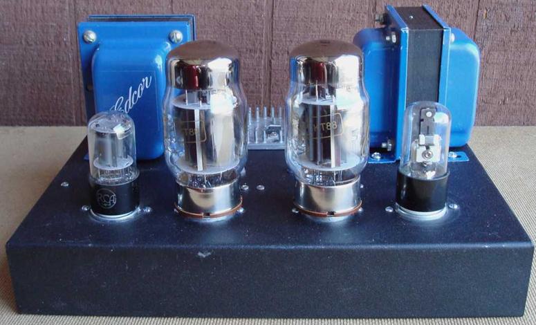
This Class A push-pull tube power amplifier uses a pair of push-pull Class A ultra-linear monotube amplifiers that can be used with several different tubes, including KT77/6L6GC/KT88, paired with 12SL7 driver tubes and 6NO30 tubes. The amplifier stage is based on a compact high-fidelity power amplifier. One thing about DIY audio is that it's a journey, not a destination, and it never ends. One project leads to another. The only limitations are time and money. DIY audio is largely about perfection. While I'm quite happy with my previous tube amplifier project, I feel there's still room for improvement (and the journey continues). I love immersing myself in the music. If anything stands out, it diminishes the experience. So I tend to prefer a smooth response, a wealth of detail, a wide soundstage, and a full-spectrum sound. These amplifiers deliver all of that in quantity. Regardless of what output tubes I use, the sound is "silky" and refined.

The previous project, the OddWatt 225 (6SL7 SRPP / KT77 Class A push-pull tube amplifier), had a beautiful tube sound in everyday use (with JJ KT77 tubes). The Odd Blocks are very similar, except they are two separate amplifiers and were designed from the outset to be able to use any power tube with the same pinout (6L6GC, KT77, KT88, EL34, 6CA7, and all variants). TubeDepot.com has a good selection of these tubes—NOS and newer products. I initially used KT77 tubes because I was familiar with their sound, which was a good starting point. I experimented with Electro-Harmonix KT88 tubes. Using EH KT88 tubes was complicated. EH KT88s provide more power, but the sound is different from the KT77. Furthermore, they don't perform well in this particular amplifier. I suspect the cause is related to thermal issues and the use of a shared (joint) cathode bias. The circuitry allows for bias adjustment (a 25-ohm variable resistor), but the EH tubes cannot maintain synchronization. One or the other tube (it's unpredictable which one) will start conducting more current than its fair share. This is undesirable since current balance is a critical design consideration. In contrast, the JJ 6L6GC and JJ KT77 tubes balanced and remained stable within 1 mA. This might just be the case with a particular brand of KT88. I later purchased a new set of Gold Lion KT88 tubes, and they performed perfectly. I won't speculate further on why one brand works while the other doesn't. That's how it is. For a more complete description of how the two stages of the amplifier work, see the original OddWatt project (ECC802S SRPP / EL84 (6BQ5) Push-Pull Tube Amplifier). The SRPP driver stage and SIPP output stage work very well together. The alternative driver tube for the 9-pin application is the 5751. This tube can directly replace the octal 12SL7 in this circuit. Other tubes with the same base as the 5751 (12AU7, 12AT7, and 12AX7) have been tried, but none have performed as well as the 5751.
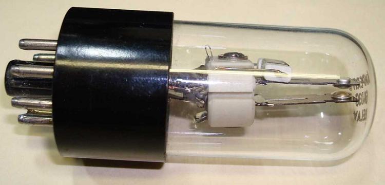
6NO30 thermal delay relay vacuum tube
Photo 2: 6NO30 thermal delay relay tube
As with almost all vacuum tube projects, dangerous voltages are used. Contact with any point in this circuit can be fatal. This may not be a suitable project if you are unfamiliar with vacuum tube equipment or do not have experience with high voltage.
This is a pair of monoblock amplifiers—each with its own power supply. In some ways, it's more complex and expensive, and in others, it's cheaper, easier, and has advantages. First, if you only need one amplifier, then you only need to build one. Second, if you need three (possibly one for a subwoofer), then you can build three. In the stereo version, it requires two power transformers, rectifiers, and filters. But the transformers are cheaper than those needed for a single-chassis stereo amplifier. An added benefit is that you don't need a set of wheels to move the amplifier. A single-chassis amplifier would weigh over 50 pounds.
SRPP/SIPP tube amplifier design with CCS
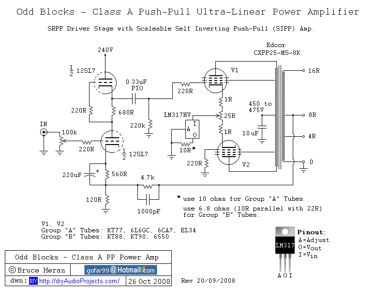
For design purposes, I found the potential power transistors to fall into two broad groups. Group "A" includes the KT77, 6CA7, EL34, 6L6GC, and similar variants. Group "B" includes the KT88, KT90, 6550, and their variants. The differences lie in the bias voltage and maximum power dissipation. I have described these differences in the Measurement and Listening sections. The basic circuitry is the same as the previous Oddwatt amplifier (see other projects). I have no reason to break a good design. However, there are some improvements. The CCS in the original amplifier was a standard LM317 voltage regulator IC. I later switched to the LM317HV. The voltage breakdown margin is better. I know these are discontinued, but there are plenty available in parts libraries. In fact, only version "B" requires it. Version "A" can use the standard LM317. So far, I haven't received any reports of failures in any applications, but I am concerned about the 37V rating of standard parts in KT88 applications. Some resistor values in the SRPP stage have been changed to increase current flow. Other DIYers have determined that this slightly reduces the distortion level. This makes sense, but measurements to date haven't confirmed it because the levels are already quite low. The power supply uses an Edcor 180-0-180 transformer with full-wave bridge rectification across all windings. Capacitor input filtering is used, with B+ between 450V and 475V. I tried a 1-Henry choke for filtering but deemed it not worth the cost and failed to significantly improve the filtering.
12SL7 SRPP KT88 Push-Pull Tube Amplifier Circuit Diagram
Figure 1: Circuit diagram of OddBlocks - 12SL7 SRPP / KT88 push-pull tube amplifier
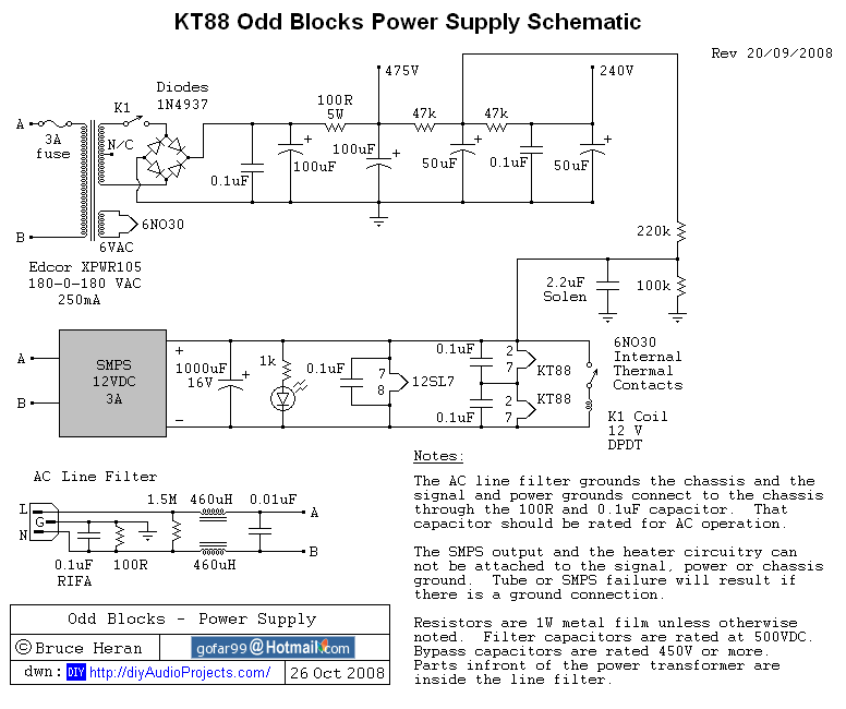
12SL7 / KT88 tube amplifier power supply circuit diagram
Figure 2: OddBlocks - Power Supply Circuit Diagram
Part of DIY is that you can do things manufacturers won't do. I found a source for the 6NO30 "tube". For those unfamiliar, it's a thermal relay in an octal socket. It's a fairly old-fashioned gadget. It's the same size and shape as the 12SL7, thus adding a nice symmetry to the amplifier. These "tubes" work on the principle of a heating element and a bimetallic switch. The contacts are rated for 500,000 operations at full power. Unfortunately, the contact voltage is rated at 120 VAC (the breakdown voltage was rated at 500 volts when new—whatever that means). Obviously, that's not high enough for switching 360 volt AC. So, I used the contacts to activate a 12-volt relay, actually doing the work of connecting the AC (360 volts) to the rectifier. The 6NO30 will activate with a 30-second delay. Thermal relays of other values are also available. These are inexpensive ($2.96 each) NOS. They are numbered as follows: the first few digits are the heater voltage. Then comes NO or NC, indicating whether the internal contacts are normally open or normally closed. The last number indicates the delay in seconds. Using a thermal relay might be a sign of madness; the work could be done much more simply with transistors and some passive components, but it is undeniably cool. The rest of the power supply is similar to my other projects. I used a generic, inexpensive 12-volt, 3-amp SMPS to power the heater because it's cheap, very compact, and provides a clean, well-regulated power supply. Traditional transformers, rectifiers, and filters can be used. The Edcor power transformer has a 6-volt winding, which is satisfactory for group "A" tubes. For group "B" tubes, a larger transformer would be needed. Generally, it's slightly easier (and cheaper) to get the required power at 12 volts 2 amps than at 6 volts 4 amps. The losses are lower. Alternating current can also be used for the heater. It will likely add a bit more noise floor. If you're like me and hate hum and noise, I'll stick with SMPS for the heater unless it's a "budget" build for these amplifiers.
Construction - OddBlocks tube amplifier
The build was fairly straightforward. The chassis is steel from Hammond, purchased from Antique Electronic Supply. The transformer is from Edcor. Wiring is point-to-point, and I used some terminal boards (aka turret boards) for connections. More sensitive circuitry was kept as far away as possible from the power transformer and noise sources. Filter capacitors and B+ relays are glued to the chassis. A notable feature is the use of a ground bus (visible as thick bare copper wire in the photos). This has effectively minimized the possibility of hum, noise, and ground loops in past projects. Special precautions were taken regarding the heater circuitry. I discovered some time ago that it's easy to exceed the heater-cathode voltage rating of the drive tube when using an SRPP design. Several possible solutions exist. I used one that biased the heater at approximately one-third of the 240V supply. No current flowed (only tiny leakage in the microamp level). There are two extremely important considerations with this approach. First, no part of the heater circuitry can be grounded. Second, the heater power source cannot be grounded either. It needs to be floating, similar to the heater circuitry of many tube rectifiers. If you're using an SMPS, it needs output isolation from input and not grounded in any way. If not, the fault is almost guaranteed. Another important point in the build is the CCS connection. The LM317HV's "adjustment" terminal is grounded. The sense resistor is between the output terminal and ground. This is different from using the IC as a voltage regulator. When correctly connected, the current equals 1.25 divided by the resistance value (ohms). Therefore, 10 ohms will result in 0.125 amps of current flowing. The CCS needs heatsinking because it must handle up to 8 watts of dissipation (when using the KT88 at 180mA—other tubes and less current). Now there's some magic; if you use a fixed 10-ohm resistor in the CCS for the basic setup, it will result in close to 62 mA per tube. If you have a 22-ohm resistor in parallel with it via a simple SPST switch, you can boost the current to 90 mA per tube. The first setup is perfect for group "A" tubes, and the second for group "B". Tube swapping is very easy in this amplifier.
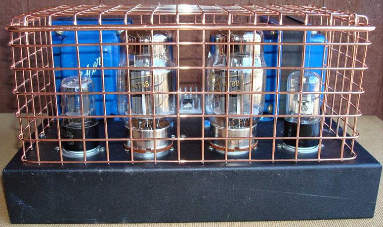
12SL7 SRPP / KT88 Push-Pull DIY Tube Amplifier
Photo 3: 12SL7 SRPP / KT88 Push-Pull Tube Amplifier - Internal View
For additional tube amplifier design and construction tips, please see my Tube Amplifier Design and Construction Tips and Suggestions. Additionally, I have published some suggested tube amplifier wiring color codes that you can use in your construction.
Testing and Operation
Before actually listening to the amplifier, it's important to verify that the heater and B+ power supply are working. There are critical voltages in this amplifier, so be extremely careful when making any measurements. I recommend installing a 6NO30 (if you're using one) without any other tubes. Turn on the power and check the voltage. There should be 12 VDC between the heater pins on the 12SL7 socket, and approximately 475 B+ at the filter capacitor. The 240 volt point will be higher (close to the 475 reading) because there's no load on the circuit. There should be no B+ before the 6NO30 is switched on (about 30 seconds). If everything is normal, turn off the power. The filter will be fully charged at this point, so be careful not to touch any part of the circuit. Insert the remaining tubes and reapply power. Observe for problems (red-hot tube plates, sparks, smoke, noise, and other interesting things indicating bad news). Check the voltage again. They should be within the appropriate range (12 VDC on the heater, 475 and 240 B+). If they are significantly different, some wiring is incorrect. If everything is OK, turn off the power and connect the speaker. Turn the power on. The speaker should have almost no sound (humming or noise). If you have a very sensitive speaker, a small amount might be okay. If you can hear it from 12 inches away, there's likely a grounding/shielding issue. I have a 93 dB/watt speaker with barely audible hum and noise when my ear is directly against the speaker grille. If all this checks out, feed the amplifier and look at the output. It should be warm, sweet tube music. Now it's time to do an initial balancing of the output tubes. The voltmeter reading at the test point should be in the range of 40-200 mV. The goal is to adjust the controls to make the readings the same for each tube. The readings should add up to the mA number set by the CCS. If you selected 125 mA, the sum of the two readings should be close to 125. Precision isn't required at this point. Let the amplifier run for at least 15 minutes and check the settings again. It might vary slightly—so reset it. I recommend checking about once a month to account for tube aging. If the tubes don't balance, swap them. Some tubes are more sensitive to grid ground. It's almost always possible to balance them. If the tubes don't balance, it's likely either a wiring error or the tubes are out of tolerance. Matching transistors are not necessary, but if the price is right, making them closer together and easier to balance is preferable. I've found that not all companies balance transistors the same way, and sometimes a "matched" set doesn't work as well as a randomly selected transistor. This circuit balances them at fairly high idle current. Many companies use small current values or test based on maximum voltage and current. Personally, I've had good luck with JJ transistors and poor experience with EH KT88s. Just to make sure no one gets too excited, it might not be EH's fault. Not all transistors work well in all circuits, and EH KT88s might work well in other designs. The ones I have just don't work well in this instance. Gold Lion KT88s work well, so this isn't a fundamental property of the KT88 design itself.
One area that always seems to cause problems is the phase of the feedback loop. In one direction, it will be "negative feedback," and in the other, "positive feedback." Negative feedback stabilizes the amplifier's gain and response. Use only a small amount. It also handles any possibility that might excite the output transformer to resonate at around 60 kHz. Positive feedback will do the opposite. The simplest way to check this without testing equipment is by listening. If the feedback is negative, the output will be slightly lower than when it's off. If the output is higher, it's positive. This is easily visible on an oscilloscope when you feed in a small signal. Using a small amount will only reduce the volume slightly (about 3-6 dB). I received a message from another DIYer using a different output transformer. His high-frequency response dropped significantly. In this case, I suggest trying a lower NFB capacitor value (1000 pF). The exact values for the resistor and capacitor are based on the Edcor transformer. If you are using other brands, you may have to experiment with the values.
12SL7 SRPP / KT88 Push-Pull DIY Tube Amplifier
Photo 4: Odd Block tube amplifier with cover removed
Measurement - Push-pull KT88 tube amplifier (12SL7 driver)
Measurements were performed using an HP 331A distortion analyzer, a Tenma low-distortion signal generator (0.05% residual THD), and a Velleman PCSU1000 (PC interface) oscilloscope. The results for the tested amplifiers were remarkably similar to those for the OddWatt 225 (6SL7 SRPP/KT77 Class A push-pull tube amplifier). This is not surprising, as they are quite similar. Using an 8-ohm resistive load, the response was measured from 8 Hz (the lowest I could generate) to 19 kHz (at -1 dB). The -3 dB point was at 30 kHz. The Gold Lion KT88 tube rose by +0.5 dB at 10 Hz, while the JJ KT77 tube flattened out at that frequency. Distortion was 0.14% or less across the entire frequency range (at one watt, see later comment). For group "A" tubes, the output before distortion was 15 watts visible on the oscilloscope, depending on the specific tube used. Up to 20 watts is possible. For tube group "B", the corresponding output is 24 watts, with noticeable distortion around 30 watts. As expected, the distortion is almost entirely harmonics. They are typically suppressed by about 50 dB. The hum and noise are below -74 dBV, which is the noise floor of my current test setup. It's almost entirely broadband noise. At one watt, the distortion harmonics are buried in the noise floor. For those who like graphics, I've included a spectrum analyzer screenshot of a 1000 Hz sine wave and some square wave images. I only included the square wave response images because the sine wave images are a perfect copy of the input signal at all frequencies. I ran into problems when I wanted to run the full distortion profile. Just before I started, I discovered noise in my store's AC power supply. Noise tends to confuse HP analyzers. Initial results were below 0.15%, and I don't want to make any further claims until I cleared the noise issue. Instead, I ran a bunch of high-power oscilloscope tests. The KT88 versions can deliver 24 watts of square wave from 20 Hz to over 10 kHz. They look very similar to those at one watt.
As I've noted on several occasions, this is a difficult topic to address. What I hear and like is almost certainly different from what others hear and like. I like to be immersed in music. If there's anything glaring, it diminishes the experience. So I tend to prefer a smooth response, a wealth of detail, a wide soundstage, and a full-spectrum sound. These amplifiers deliver all of that in terms of quantity. The sound is “silky” and refined, regardless of what output tubes I use. At the same time, it has very solid bass. That's almost good enough for me to turn off the subwoofer. Yes, I admit to using a subwoofer. Two massive 7 cubic foot cabinets with 15-inch drivers. They are powered by a DIY LM3875 non-inverting chip amplifier (gainclone) kit, with the signal split at 50 Hz via a 24 dB/octave Marchand electronic crossover. The main speakers are a pair of modified Altec Lansing 1010s. The sound using only the main speakers (full-range, no crossover to the subwoofer) is full and solid. There's enough bass for anyone except someone like me. I love those minimum two octaves. The imaging is excellent, the center is very stable, the separation is limited only by other devices (they are, after all, monoblocks), the detail is excellent, and the sound has the warm quality you'd expect from a tube amplifier. Personally, I feel the JJ KT77 tube has the most refined sound quality, while the JJ 6L6GC and Gold Lion KT88 tubes have the best bass. The KT88 tube is, of course, louder.
Reflection
After a project is completed and working, I always have some thoughts. For example, was it easy to build? As a DIY project with point-to-point wiring, it's not particularly easy for beginners. For more advanced builders, it will be easy. This isn't the best option for a first project. Is it worth the cost and time? I think so. Transformers and tubes are the main expenses. About $150 per channel. The remaining parts depend on the builder. It can be as low as $75 or as much as possible. I use mid-to-high-end parts, estimating about $150 per channel. High-end tubes (Gold Lion KT88, etc.) will cost more. Can you buy a tube amplifier with this sound quality for $300 per channel? I don't think so. I won't get involved in the debate about whether an SS amplifier can do the same thing at a lower cost. That's for other people to decide.
- TDA1011 6.5W Power Amplifier
- 50W LM3886 Power Amplifier
- Miniature audio amplifier
- 25-watt MOSFET audio amplifier
- Portable microphone preamplifier
- Two transistor microphone preamplifier, triode amplifier circuit
- Connection between power supply and voice integrated circuit
- A simple tone generator circuit
- Using LM3886 to make a 50W high quality power amplifier circuit
- Make a pocket amplifier with 8550 and 8050
- Current amplifier circuit structure diagram
- TDA7056A power amplifier circuit diagram
- TDA2822M power amplifier circuit diagram
- TDA2822 power amplifier circuit diagram
- TDA1905 power amplifier circuit diagram
- TDA2005 power amplifier circuit diagram
- TDA1519A power amplifier circuit diagram
- TDA1510A power amplifier circuit diagram
- STK461 power amplifier circuit diagram
- STK437 power amplifier circuit diagram


 京公网安备 11010802033920号