Gain Cloning Power Amplifier LM3886
Source: InternetPublisher:CxGgCgOj Keywords: Power amplifier LM3886 Updated: 2026/03/24
Gain Cloning Power Amplifier LM3886
In this application, we are building an amplifier similar to a gain card. This type of application is known as gain cloning in the audio world. To achieve a satisfactory audio response, we added a Linkwitz equalizer to the feedback line and increased bass compensation.
We used the LM3886, a revised version of its sibling, the LM3875. These are the parameters we focused on. Frankly, these figures far surpass many hi-fi amplifiers on the market. A signal-to-noise ratio of 110dB is particularly rare. Another characteristic is that the amplifier is almost silent when there is no input signal. Even with your ear close to the speaker, you can barely hear any noise.
We will be performing a similar application to a gain card. In the DIY audio application field, this type of cloning is called a gain card cloning. To provide a satisfactory response for audio feedback applications, we added simple Linkwitz equalization compensation to the bass line.
It uses the newer revision of LM3875, LM3886.
Maximum output power: 68W RMS - 108W peak
THD: 0.03% @ 60W
SNR: 110dB @ 60W - 92.5 dB @ 1W
PSRR: 120dB
Protection circuits: DC/AC short circuit protection, thermal protection
Output stage: Conjugate EU-A class
These are the parameters we're focusing on. Clearly, these figures are among the best in the market for most Hi-Fi amplifiers. The 110dB signal-to-noise ratio, in particular, is extremely rare. In short, if the amplifier is set up correctly, you won't hear any hiss or noise even when close to the speakers with no input signal. In other words, the amplifier is completely silent when there's no signal input. Furthermore, even when running continuously at full power with the recommended speaker setup, there is virtually no distortion. The performance is even better.
Now let's look at the circuit diagram... National semiconductor engineers have proposed the following basic application circuit.
We will be performing a similar application to a gain card. In the DIY audio field, this type of cloning is called gain card cloning. To improve audio feedback response, we applied a simple Linkwitz equalizer in the bass circuitry.
The new revision LM3886, which integrates LM3875, will be used.
Maximum output power: 68W RMS - 108W peak
THD: 0.03% @ 60W
SNR: 110dB @ 60W - 92.5 dB @ 1W
PSRR: 120dB
Protection circuits: DC/AC short circuit protection, thermal protection
Output stage: Conjugate EU-A
The parameters we focused on are as follows. These values are clearly superior to most Hi-Fi amplifiers on the market. In particular, the 110dB signal-to-noise ratio is rarely seen in the market. In short: if this amplifier is set up correctly, no noise can be heard even when close to the speakers when there is no input. In other words, this amplifier is completely silent when there is no signal input. Even when continuously driving the recommended speaker group at full power, there is almost no distortion.
Now we come to the circuit diagram section... The basic application circuit recommended by the National Semiconductor Engineers is as follows.
The circuit diagram is remarkably simple and easy to implement. No modifications were made to the signal lines to avoid introducing noise. In the circuit, Rin is the input level potentiometer, Rb is the current-limiting resistor, and Ri and RF1 are the gain resistors. This application achieves a gain of 20K/1K = 21 times (26.4dB). The 22μF capacitor ensures feedback gain flatness by providing an initial roll-off of approximately 7Hz, eliminating low-frequency speaker propagation limitations.
Our application is as follows:
As can be seen, the negative feedback circuitry has been significantly modified. This results in a peak gain of approximately 7dB in the 30Hz-70Hz frequency range, and an increase of approximately 34dB at 30Hz. Designed by Nico Ras, this circuit is suitable for 16 or 20cm wide, 10-15 liter sealed enclosure subwoofers, effectively compensating for the frequency response drop that typically begins at 70-80Hz, and maintaining the low-frequency cutoff (F3) in the 40-50Hz range. The advantages are evident when considering high-quality compact subwoofer systems with an F3 close to 40Hz. However, users seeking extremely low frequencies (20Hz) will need to design an active subwoofer system separately. The application circuit delivers an average output of 65W RMS power with a 26V DC power supply, a 4-ohm speaker, and a 2Vpp input signal. Users with 8-ohm speakers can increase the power supply voltage to ±38V. These values can also be used with lower voltages.
The power supply circuit is also simple:
A "π-type" filter is constructed using dual secondary transformers, two KBU6 series (6A) diode bridges, and two 10000μF inductors and capacitors. A general rule is that 2200μF of capacitor per ampere is sufficient for the voltage regulation requirements of Hi-Fi applications; in this example, 4700μF of capacitor per ampere is used. Based on an average of 2 amperes per channel, it is recommended that users operating at continuously high power (above 80%) use two 10000μF capacitors per channel.
Transformer Selection: Toroidal transformers are commonly used in Hi-Fi applications. These transformers are more expensive (60-80 Euros) but save space, and their low flux leakage allows them to be installed in the same enclosure as the amplifier. If the amplifier and transformer are placed in separate enclosures, a standard EI type transformer can be used. The transformer specifications must at least meet the following requirements:
- 8-ohm standard application: 220V/2×24V (with center tap) at least 250W
- 8-ohm high-power mode: at least 350W at 220V/2×24V
- 4-ohm standard application: 220V/2×18V minimum 250W
- 4-ohm high-power mode: at least 350W (220V/2×18V)
Transformer power selection criteria: 68W RMS output power plus at least 20% instantaneous peak power reaches 81W. Considering the 60% efficiency of a Class AB amplifier, at least 135W is required. Simultaneous operation of both channels requires 270W of power. In practice, 250W is sufficient for typical 2x20W listening needs. In high-power mode, each channel continuously delivers over 55W, requiring 180W per channel to match the peak power of hard rock music. In such environments, good heat dissipation for the transformer and circuitry is crucial.
Implementation:
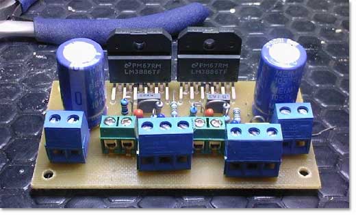
The circuit is made very simple to implement through a carefully designed printed circuit board.
The front view shows a compact structure, though slightly crowded, but far removed from noisy design. This characteristic is particularly enhanced by keeping the NFB (negative feedback) line short. This circuit configuration has been tested and yielded good results.
The installation process is smooth, but note that all input and output terminals should use printed circuit board terminals. 1% precision metal film resistors must be used; otherwise, the same results will not be achieved.
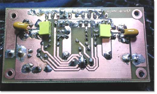
The rear view shows that components must be mounted on the soldering side. Power lines must be kept short; this can be achieved through post-assembly. Integrated circuit power pins must be pre-tinned. While time-consuming to implement, it is not difficult.
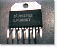
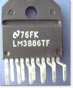
It should be noted that there are two versions of the LM3886: the LM3886TA with an insulating housing and the LM3886TF without an insulating housing. This application uses an insulating gasket and thermal grease for direct connection to the heatsink. Users of the TA version must use an insulating gasket and thermal grease, and ensure that the mounting bolts are insulated from the heatsink.
The power supply printed circuit board is as follows:
This board features a simple design, including four PCB terminals, two KBU6 series diode bridges, and two 10000μF/35V capacitors. It will be mounted in the same chassis as the amplifier and connected via DC1 and DC2 shorts.
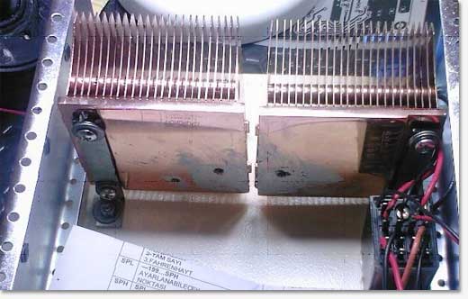
Cooler Selection: TA version users require a 2.8°C/W cooler, which is approximately 5cm x 10cm aluminum heatsink with 8 or more fins. TF version users require a 1.8°C/W cooler, equivalent to twice the size. Smaller copper heatsinks can also be tried. This application uses two fanless copper heatsinks connected together for the AMD Athlon processors.
A standard heatsink costs 50-100 yuan, with a total cost of approximately 35 yuan for the solution... This configuration passed the temperature rise test during an average two-hour rock music session (approximately 20W x 2). Test method: After two hours of operation, if a finger can continuously touch the IC surface for more than 10 seconds, the heat dissipation is considered合格 (qualified). The heatsink surface temperature should be close to the IC temperature. If measured with a thermocouple, the surface temperature should be below 65°C; otherwise, thermal protection will be triggered. If the IC overheats while the heatsink remains cool, the connections and thermal paste need to be checked.
Note: The relay in the image on the right is a power relay. It controls the synchronous switching of four channels (DC1+/- and DC2+/-) via a front panel microswitch; installation is recommended.
Assembly:
Collect all circuit boards into one or more enclosures and secure them in place. Wooden, plastic, or metal enclosures are recommended, and each enclosure must have ventilation holes. Allow sufficient space behind the enclosure.
The back panel requires connection to three terminals/ports: a 4-pin power connector (or a 4-pin PC hard drive connector), a standard speaker connector, and an RCA signal input connector. For single-input, single-channel amplifiers, single input is recommended to maintain the lowest possible noise.
The signal cable connection is the most critical; improper handling can lead to noise.
- The RCA signal input interface connects to the enclosure via the shortest path and directly connects to the amplifier circuit board using fine-core audio codec terminals.
- The left and right channels of the same RCA connector are connected to the far end of the volume potentiometer via a shielded cable (LIYCY).
- The potentiometer's midpoint is connected to the audio encoding terminal via a short wire, and the cable shield is grounded at one end.
- It is absolutely forbidden to share a ground with two independent shielded wires.
- The RCA connector housing must be grounded.
- Never operate a potentiometer without a load, as this will cause the integrated circuit to oscillate and burn out the tweeter.
- When using the LM3886TA, insulating gaskets and bolts must be installed. Before powering on, the metal parts should be measured to be open circuits.
- A 100Hz buzzing sound will be generated if the signal loop forms a ground loop with the chassis.
Speaker connection: Connect the (+) terminal to the CMB encoding terminal (the only multi-pin terminal). The GND-RET encoding terminal is the power distribution point. Signal lines must not be connected to this point. It can be connected to the chassis through a single-point grounding connection.
Finally, please note: Use at least 1.5mm² cross-sectional area multi-core wire for power and speaker connections, otherwise there is a risk of overheating.
speaker:
The final speaker selection should be based on high-quality components and calculation criteria. It is recommended to choose the best possible woofer and tweeter.
Choose a 4- or 8-ohm woofer, with a diameter of at least 16-20cm, and never use a subwoofer unit. The frequency response curve should extend at least to 3kHz for good integration with the tweeter. Subwoofers generally only have a frequency response up to 500Hz-1kHz and perform poorly.
The tweeter unit must have the same impedance (4 or 8 ohms), and a dome tweeter with at least 50W power is required. Piezo tweeters are absolutely not recommended.
Passive crossover uses only series-connected non-polarized capacitors. Prepare capacitors ranging from 1μF to 10μF, and select the appropriate capacitors to connect in series with the tweeter based on listening experience.
Cabinet construction (not relevant to this design): Simplest part: Use 18mm particleboard or MDF, 10-liter bass driver cabinet volume (15-20 liters recommended). Example 10-liter cabinet dimensions:
Front panel width 20cm
25cm deep
Height 30cm
The volume occupied by the speaker needs to be considered.
The front panel of the enclosure has openings for mounting the woofer and tweeter units, while the rear panel houses the wiring terminals. Key points: The enclosure is filled with sound-absorbing cotton (not too tight or too loose), and all seams are sealed with silicone to prevent air leakage during speaker installation.
Finally, please note: the amplifier gain remains at 26dB (20x), which may be insufficient for some low-level outputs (such as iPod). If users report insufficient volume, a preamplifier can be added later.
Wishing you a successful production.
PhD
Materials list
semiconductor:
LM3886TA (TF) 2
KBU608 2
capacitance:
10000μF 35 (50)V 2
1000μF 35 (50)V 2
4 x 10μF 35 (50) V tantalum capacitors
Two 2.2μF 35 (50) V tantalum capacitors
470nF 63V Polyester Capacitor (1 piece)
Two 100nF 63V ceramic capacitors
Two 150nF 63V polyester capacitors
resistance:
20kΩ 0.6W 1% Metal Film Resistors (2 pieces)
20kΩ 1/8W 5% carbon film resistors (2 pieces)
15kΩ 0.6W 1% Metal Film Resistors (2 pieces)
10kΩ 0.6W 1% Metal Film Resistors (2 pieces)
1kΩ 0.6W 1% Metal Film Resistors (4 pieces)
2.2Ω 1/4W 5% Carbon Film Resistor (1 unit)
other:
10kΩ×2 Dual Logarithmic Potentiometer
2×18 (24) V toroidal or EI type transformer (250 or 350W) with center tap
Radiator with a temperature not lower than 2.8°C/W
RCA terminal
speaker terminals
4-pin power connector (male/female)
Wires and other materials
- TDA1011 6.5W Power Amplifier
- General purpose 2-watt stereo power amplifier
- High-fidelity headphone amplifier
- High-performance stereo audio amplifier using LM3886
- Portable tube headphone amplifier
- Low voltage multi-song music integrated circuit using K482G
- TDA7264 audio power amplifier circuit
- TDA2030A subwoofer circuit diagram
- LM1876 single power supply audio power amplifier circuit
- Single music integrated circuit with power amplifier composed of HY-1
- Qorvo adds GaN power amplifier
- TDA7285 power amplifier circuit diagram
- TDA7233S power amplifier circuit diagram
- TDA2822 power amplifier circuit diagram
- TDA2004 power amplifier circuit diagram
- TDA1554Q power amplifier circuit diagram
- TDA2005 power amplifier circuit diagram
- TA7368P power amplifier circuit diagram
- TA7273P power amplifier circuit diagram
- TA7241AP power amplifier circuit diagram


 京公网安备 11010802033920号