Equivalent Series Resistance and Low Resistance Tester
Source: InternetPublisher:0BNOaY8ui Keywords: Tester resistance tester Updated: 2025/12/05
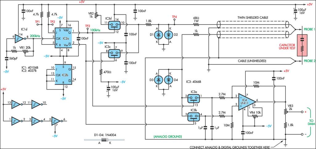
As electrolytic capacitors age, their internal resistance, also known as "equivalent series resistance" (ESR), gradually increases. This can eventually lead to equipment failure. Using this design, you can measure the ESR and other small resistances of a suspected capacitor. Essentially, the circuit generates a low-voltage 100kHz test signal, which is applied to the capacitor through a pair of probes. An operational amplifier then amplifies the voltage drop across the capacitor's series resistance, which can be displayed on a standard multimeter. More specifically, the inverter IC1d is configured as a 200kHz oscillator. Its output drives a 4027 JK flip-flop, which halves the oscillator signal to ensure equal duty cycles. Two elements of a 4066 quad bidirectional switch (IC3c and IC3d) are alternately switched by the complementary outputs of the JK flip-flops. One switch input (pin 11) is connected to +5V, while the other (pin 8) is connected to -5V. The outputs of these two switches (pins 9 and 10) are connected together, resulting in a ±5V 100kHz square wave. A series resistor is included to limit the current before the signal is applied to the capacitor under test through the pair of test probes. Diodes D1 and D2 limit the signal swing and protect the 4066 output when the capacitor is energized.
The second pair of leads detects the signal generated at the probe tip. Again, the signal, limited by diodes (D3 and D4), is applied to the remaining two inputs of the 4066 switches (pins 2 and 3 of IC3a and IC3b). These switches alternately feed half-cycles to two 1μF capacitors, removing most of the AC component of the signal and providing a simple "sample and hold" mechanism. The 1μF capacitors are charged to a DC level proportional to the ESR of the capacitor under test. This is differentially amplified by operational amplifier IC4 so that it can be displayed on a digital multimeter – 10Ω will correspond to 100mV, 1Ω to 10mV, and so on. When calibrating the circuit, VR1 is first adjusted to obtain 100kHz at TP3.
Next, momentarily short the test probe and adjust VR4 until pin 6 of IC4 is 0mV. Afterward, set the multimeter to read milliamps and connect it between TP4 and the negative DMM output. Apply -5V to TP2 and observe the current; it should be approximately 2.1mA. Transfer the -5V from TP2 to TP1 and adjust VR2 until the same current is obtained (ignore the sign). Remove the -5V from TP1. Set the multimeter to read the voltage again and connect it to the DMM output. Apply the probe to a 10W resistor and adjust VR3 until the reading is 100mV. Finally, ensure that all capacitors under test are fully discharged before connecting the probe.
- LC measuring instrument based on AVR microcontroller
- Current sensor
- Music logic test pen
- Extending Current Measurement Range with Resistor-Free Sensing Solutions
- Using sub-milliohm resistors for current sensing has its advantages but also presents challenges
- How to Accurately Measure Current and Voltage in GSM Systems
- Design and production of logic detectors
- Humidity measurement circuit with temperature compensation
- A sensitive voltmeter made with an operational amplifier
- Key points for designing industrial 4-20mA power supply and current collection
- Valuables detection circuit design
- Remote control infrared detection circuit
- Using window discriminator as intensity detection circuit
- Three-phase AC phase sequence detection circuit
- Combustible gas concentration detection circuit
- Cable automatic detection circuit
- ADM690~ADM695 constitute a detection circuit (2)
- Light sensor particle size distribution detection circuit
- Human body detection circuit for infrared sensor
- Ferromagnetic material proximity detection circuit


 京公网安备 11010802033920号