Oscilloscope-type ESR tester
Source: InternetPublisher:xNP9AP5UE Keywords: ESR tester Updated: 2026/01/13
Oscilloscope ESR tester
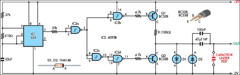
When used with an oscilloscope, this simple circuit provides a method for measuring the ESR of a capacitor.
A 555 timer (IC1) is configured as a 2.3kHz free-running oscillator as the time base. It provides a narrow (7.7µs) pulse to the capacitor under test via a NAND Schmitt trigger (IC2) and transistor Q1.
A 100Ω resistor is connected in series with Q1, limiting the current to approximately 50mA. Therefore, an ESR of 1Ω will generate a 50mV pulse across the test capacitor, meaning that an oscilloscope with a vertical sensitivity of 5mV can measure ESRs as low as 0.1Ω or lower.
Transistor Q2 discharges the test capacitor during the "off" portion of the test cycle, ensuring zero average DC component. Diodes D1 and D2 limit the maximum output voltage to approximately 0.6V, corresponding to an ESR of 12Ω, which is sufficient for most applications.
If high precision is not required, the circuit can be powered by four AA batteries instead of a regulated 5V power supply.
Testing the ESR of electrolytic capacitors
I recently discovered a simple and inexpensive way to test the ESR (Equivalent Series Resistance) of an electrolytic capacitor in a circuit, which could save many people a lot of time. It only requires an oscilloscope and a simple signal generator.
I have an oscilloscope I'm trying to repair (the intensity control is barely effective; at high frequencies, the horizontal sweep only covers half the screen. One power rail is too low, the others too high). I've checked each electrolytic capacitor in several/many different ways (all in the circuit), even comparing each reading to those of the same device: With power off: I checked the signature of each capacitor with a component tester (single-curve tracker), and performed resistance checks from the capacitor terminals to ground with a digital multimeter, capacitance checks with a digital multimeter, and checked the resistance from the capacitor terminals to ground. With power on: I connected the oscilloscope across each capacitor, and measured the DC and AC voltages across each capacitor from the capacitor terminals to ground with a digital multimeter, as well as the voltage from the capacitor terminals to ground. I did find some bad capacitors (and other bad components) and replaced them. But the problem persists!
I'd been wanting to order an ESR meter but hadn't done so yet, and I needed to fix this oscilloscope immediately. I visited Sam Goldwasser's excellent repair FAQ website and found a great method for testing the ESR of capacitors in a circuit, requiring only a signal generator and an oscilloscope (along with some cables), and found and fixed the problem in about ten minutes!! Here's what I did (the technique is basically directly from Sam's repair FAQ website):
I set up what I'll now call the "ESR oscilloscope" using a signal generator and an oscilloscope: At the generator's output, I connected a BNC "T" adapter. From the T-connector, I ran a 50-ohm BNC cable to a good (Tek 2465A) oscilloscope (which has a 50-ohm BNC terminating resistor at the oscilloscope input). On the other side of the T-connector, I connected another BNC cable with an alligator clip at one end (it's probably a 75-ohm cable; shouldn't matter too much?), which I clipped onto a banana plug of a set of cheap digital multimeter-type probes.
(Termination resistor note: I used a Tektronix 50-ohm "through" termination resistor at the oscilloscope end of the BNC cable. However, you can also use another BNC "T" connector at the oscilloscope input with a "cap" termination resistor on one side and the cable on the other. A standard 10BaseT Ethernet 50-ohm coaxial termination resistor (and 50-ohm Ethernet BNC coaxial cable) should work fine. They are available at Radio Shack and possibly Staples, etc.)
I set up a signal generator to produce a square wave of approximately 100 kHz, and observed a peak-to-peak amplitude of approximately 100 mV on the connected oscilloscope with no DC offset (a simple 555 timer circuit could also accomplish this!). Then, I set the oscilloscope's vertical sensitivity to 5 mV/div, the time base to 1 microsecond/div, and AC coupling to the input.
When the probes are shorted together, the oscilloscope displays a height of about one division. It's basically a square wave with large, narrow peaks at each leading edge. But I'm only looking at the peak-to-peak amplitude of the horizontal portion.
This is the whole setup! No resistors. Nothing else. Just cables (and a terminating resistor). I also tried putting a decimal resistance box in series with the probe, just to see what it would look like. On the oscilloscope display, I can clearly see each increase of one ohm, whether the probe is shorted or connected across a good electrolytic capacitor.
When I bridge the probe across a capacitor in a good circuit, the oscilloscope display shows almost no change compared to when the probe is short-circuited (because, depending on the frequency, a capacitor should appear more or less like a short circuit to AC). However, when I try with a bad capacitor, the display typically extends almost completely off-screen. Furthermore, some capacitors appear to be at the edge, causing the display to increase from about one bar peak-to-peak to about three to five bars (this likely corresponds to an ESR of about 5 to 20 ohms, if I remember correctly).
In any case, within a few minutes I found another bad electrolytic filter capacitor in the power supply, two smaller bad electrolytic capacitors in the power supply, a bad capacitor on the horizontal scan switch board, four bad capacitors near the middle of the motherboard, and a few other capacitors that I can't remember now.
I wrote down every single one. The first thing I did after checking everything was replaced was replace the filter capacitor in the power supply, then power it on and check the power rail voltage. Success!!! Yes!!! They're all back to normal! Not only that, the level scan problem and intensity control problem are gone!! Fantastic!
The filter capacitor tested perfectly fine using all the other methods I described above (albeit all "in-circuit"), and in all cases, it appeared normal compared to the same capacitor on another oscilloscope. However, using this "ESR oscilloscope" method, it became immediately and completely obvious. The same capacitor on the other oscilloscope tested fine using this method (so, the previous comparison was a bad capacitor versus a good capacitor, but showing no abnormalities!). [I also noticed that after removing the bad capacitor, it tested bad in essentially the same way as when it was in the circuit, and the oscilloscope showed essentially identical. And all the other capacitors I replaced tested bad when tested outside the circuit, even using other methods.]
Of course, this "ESR oscilloscope" method isn't a perfect panacea: in some cases, the display can be difficult to interpret and potentially misleading without the same equipment for comparison. (However, as far as I recall, it worked for every electrolytic capacitor I tried, from 10 uF 10V to at least 1000 uF 100V, without the need for identical equipment for comparison.) But I haven't tried it enough. I hypothesize that adjusting the frequency for different capacitors might help, especially when testing non-electrolytic capacitors. I seem to recall that a DC offset in the signal is often used when testing ESR. I'll try that later. Sometimes increasing the amplitude of the square wave can also be helpful. But generally, I think I'd prefer it to be a low amplitude, perhaps less than +/- 0.4V, so the signal doesn't turn on any semiconductor junctions.
- Capacitor Equivalent Series Resistance Meter
- Transparent fluid detector
- AD8307 USB 0-500MHz RF Power Meter
- LC measuring instrument based on AVR microcontroller
- Simple electromagnetic field probe
- Achieving higher-accuracy battery fuel gauge performance in ultra-low-power systems
- Method for measuring leakage current through insulation resistance
- Accurate current limiter solution for smart meters
- IGBT drive circuit short circuit protection function test method 1
- HT8656 Record and Play IC
- LED lighting display detection circuit with overload protection
- Paper thickness detection circuit
- Bus door status detection circuit
- Induction cooker pot quality detection circuit
- Positive peak detection circuit
- Underwater acoustic sensor detection circuit
- Long wave infrared detection circuit
- Film thickness detection circuit using eddy current method
- Hot spot sensor infrared detection circuit
- Photodiode pollution gas detection circuit


 京公网安备 11010802033920号