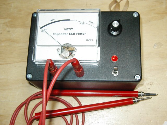
Capacitor Equivalent Series Resistance Meter
Source: InternetPublisher:e2vUtdpHn Keywords: Capacitors measuring instruments equivalent series resistance Updated: 2026/02/24
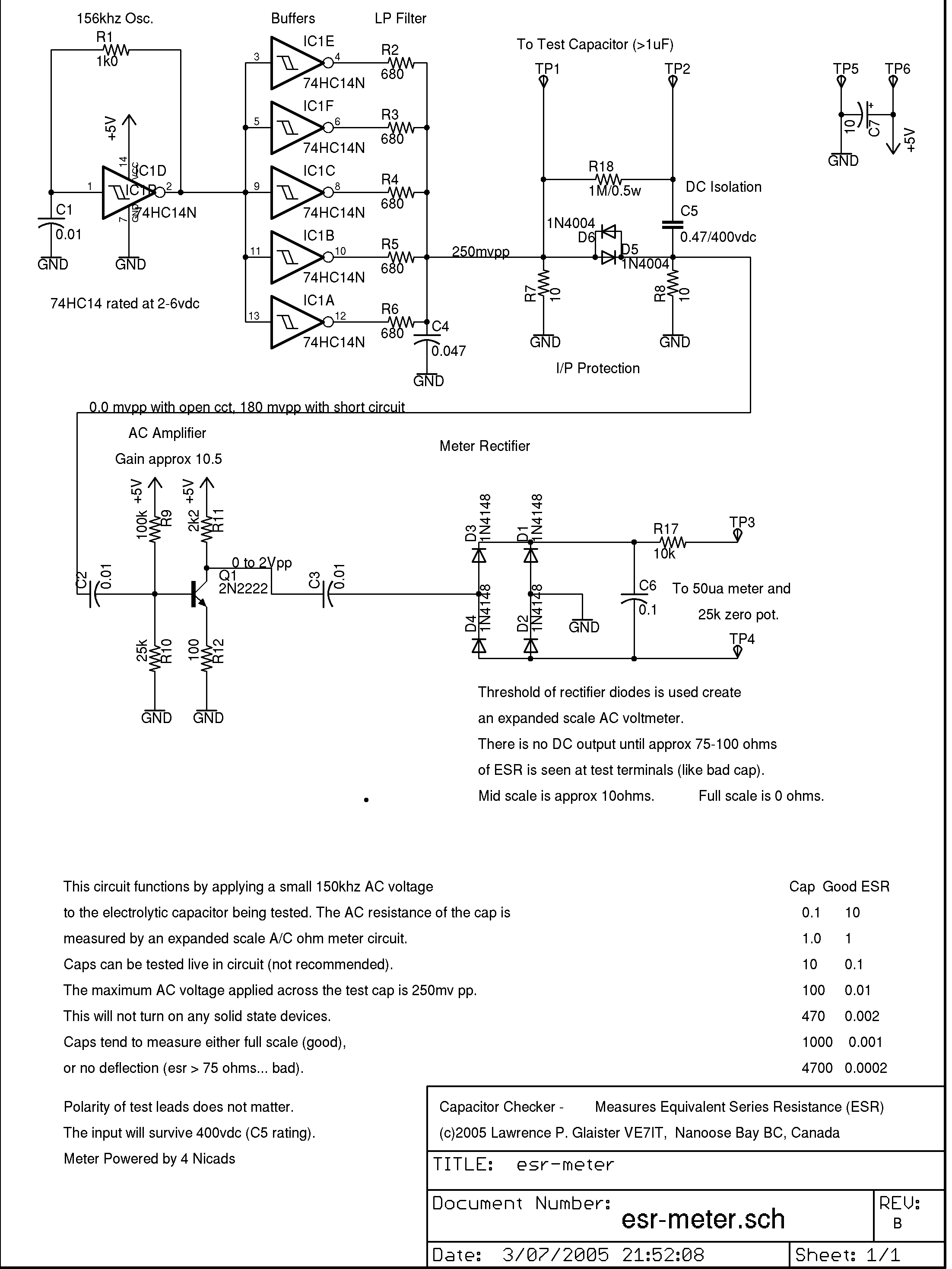
Typical capacitor testers measure the capacitance of a test capacitor (usually measured in microfarads). Some advanced units also test leakage current. Most of these testers require the capacitor to be removed from the circuit. They will not detect a high ESR value unless the capacitor is completely failed. In a typical circuit, there may be 10 or 100 capacitors. Removing them one by one for testing is tedious and carries a significant risk of damaging the circuit board. The tester uses a low-voltage (250mV) high-frequency (150kHz) AC current to read the ESR of capacitors in the circuit. In-circuit testing is possible because of the low voltage used for measurement. The voltage is low enough that solid-state devices in the surrounding circuitry will not be activated and will not affect the low resistance reading we are trying to obtain. Many capacitor testers will be damaged if they test charged capacitors. The circuit is AC-coupled and can withstand up to 400VDC of charge on the capacitor (but watch your fingers!). ESR testers will not detect short-circuited capacitors because they will read very low ESR values. If you're troubleshooting circuit faults, you'll have to use a variety of instruments, including your nose, voltmeter, and oscilloscope, to pinpoint all possible fault modes. In my experience, an ESR tester can detect about 95% of capacitor problems and potential issues.
What is ESR?
"ESR" stands for Equivalent Series Resistance. ESR is one of the characteristics that defines the performance of an electrolytic capacitor. Low ESR is ideal for capacitors because any ripple current passing through the capacitor will cause it to heat up due to resistive losses. This heating accelerates capacitor failure by drying out the electrolyte at an increasingly rapid rate. It is not uncommon for ESR to increase by 10 to 30 times or even open circuit during the capacitor's lifespan. Typical life ratings for electrolytic capacitors are 2000-15000 hours and are highly dependent on ambient operating temperature. As ESR increases, the capacitor's filtering operation is impaired, and ultimately the circuit fails to function properly.
characteristic
The electrolytic capacitors in the test circuit are greater than 1μF.
Capacitors can be tested in a circuit, or by bridging them across terminal posts or using test leads.
Polarity insensitivity test.
Capacitors that can withstand up to 400VDC.
Low battery consumption (approximately 25mA), with a battery life of approximately 20 hours when using four inexpensive AA nickel-cadmium batteries.
An easy-to-read analog table.
An AC ohmmeter with an extended scale that measures ESR from 0 to 75 ohms.
Circuit Description
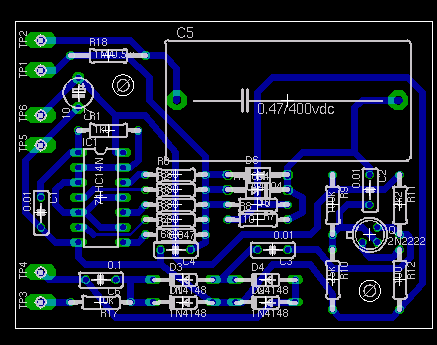
See component labels in the schematic. The circuit begins with a 150kHz oscillator, using one gate of a 74HC14. The remaining gates act as buffers to increase the current drive to the low-pass filter. A single-pole low-pass filter is necessary because the square wave signal contains a significant amount of high-frequency odd harmonic energy. The filter output is applied across a 10-ohm load resistor, which provides a low-impedance drive signal to the test capacitor. Diodes D5 and D6 protect the circuit from discharge spikes if you are testing charged capacitors. R18 is used to discharge C5 so that nothing blows up if you are alternating between testing high-voltage and low-voltage charged capacitors. C5 isolates the test circuit from DC voltages up to 400 volts.
If you are testing high-voltage capacitors, be careful... The safest way to do it is to ensure that the capacitor is discharged before testing. Note that high-voltage capacitors can retain a lethal charge for days, depending on the circuit design. I learned this in my high school electronics class. Students (anonymous!) used to charge capacitors and put them back on the shelf for the next unsuspecting victim to pick up.
The rest of the circuit is a very straightforward transistor amplifier with a gain of approximately 10.5. This amplifies the AC signal from the test capacitor to a few volts. The signal is then coupled to a full-wave bridge rectifier, which uses the meter as a load. The threshold voltage of the bridge rectifier is utilized, providing extended scale functionality for the ohmmeter. The amplified voltage from the test capacitor must be large enough to overcome the voltage drop across the two diodes for the meter to begin responding. This sets the meter's high resistance threshold somewhere between 75 and 100 ohms. The meter is zeroed by shorting the test leads and adjusting a potentiometer in the meter circuit to obtain a full-scale (0 ohm) reading. Proper circuit operation can be verified by checking several resistance values with the meter. Shorting the leads should indicate full scale, a 1-ohm resistor should read approximately 90% of full scale, a 10-ohm resistor should read approximately 40% of full scale, and a 47-ohm resistor should barely move the pointer to approximately 10% of FSD. Absolute readings will vary with temperature and battery voltage, but the idea is that most ESR values should be well less than 10 ohms, meaning that a good capacitor test is very close to full scale, while a bad capacitor test has little or no deflection.
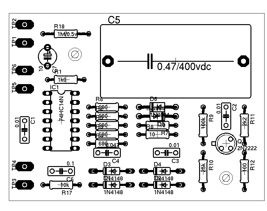
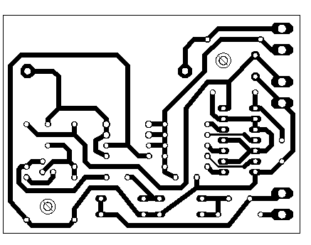
The board below shows my second prototype. The top two wires connect to the banana test jack on the front panel, the middle two wires are the 5-volt switch input from four AA NiCd batteries, and the bottom two wires connect to the series combination of the zero-position adjustment potentiometer and the meter on the front panel.
How to use an ESR tester
1. Disconnect the test leads of the ESR tester so that the probes are not in contact. Turn on the tester. If the tester has multiple modes, ensure it is set to ESR mode. The tester may perform an automatic calibration procedure when powered on. If so, wait until it indicates readiness. This may be indicated by an LED or an audible tone.
2. If the capacitor to be measured is in a circuit, ensure that the circuit is not powered. If possible, disconnect the electronic device containing the capacitor.
3. If the ESR tester does not automatically discharge, discharge the capacitor before testing. Select a high-power resistor with a resistance value between 5 and 50 times the capacitor's rated voltage. Connect the test leads to each lead of the resistor. Carefully touch the other end of the test lead to the capacitor's lead and hold for a few seconds. Use a voltmeter to confirm that the capacitor is not charged. The voltmeter should display zero.
4. Connect the test probe of the ESR tester to the capacitor leads. Read the ESR of the capacitor from the meter. It may be displayed as deflection on an analog meter, level on an LED bar meter, or a digital reading. Some ESR testers also provide an audible tone indicating the range of ESR.
5. Determine whether the ESR is acceptable by comparing the measured ESR value with the guidelines provided with the tester.
- Schematic diagram and structural analysis of oscilloscope probe
- Current sensor
- Analog Capacitor ESR Tester
- Using sub-milliohm resistors for current sensing has its advantages but also presents challenges
- How to Accurately Measure Current and Voltage in GSM Systems
- Making a simple field strength meter
- Production of moisture content detector
- HP-15 Hygrometer Production
- Using LM3915 comparator to make a light intensity meter
- Single-supply PID (proportional-integral-derivative) temperature control loop using INA326/INA327
- Overcurrent detection circuit
- Pyrothermal infrared detection circuit composed of OPA111
- Valuables detection circuit design
- Bus door status detection circuit
- New fast charging I start 2 charging detection circuit
- Remote control infrared detection circuit
- Simple phase detection circuit
- Peak detection circuit
- ADM690~ADM695 constitute a detection circuit (1)
- Direct heating gas-sensitive bridge detection circuit


 京公网安备 11010802033920号