433MHz Transmit/Receive Module RF Circuit Based on Arduino
Source: InternetPublisher:elKnu3m Keywords: Radio frequency wireless communication Updated: 2026/03/03
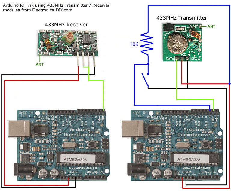
Arduino uses RF links for a 433MHz transmitter/receiver module.
If you're looking for wireless communication between two Arduino modules, this project might be helpful. It uses a low-cost RF transmitter and receiver from Electronics-DIY.com to establish a radio link between two Arduino boards over distances up to 500 feet. Data can be transmitted serially at rates up to 2400 bps. The schematic shows how the receiver and transmitter connect to two different Arduino boards. When connecting the receiver/transmitter, you simply need to power/ground them and then a pin for either TX (serial transmit) or RX (serial receive). I also connected a button to the Arduino making the transmission and used an LED on pin 13 of my Arduino board on the receiver to test the setup. The test application simply blinks the LED on the receiver board when the button is pressed on the transmitter board.
I was looking for a way to handle wireless communication between two Arduino boards. Then I found inexpensive RF transmitter and receiver modules on Electronics-DIY.com.
Here are some things to consider when using RF solutions:
- Communication is unidirectional. If you want two-way communication, you will need to purchase two receivers and two transmitters.
The variable gain on the receiver caused it to pick up a lot of background noise. I had to do some processing with the Arduino to filter out this noise. More details are in the code section below.
The maximum bandwidth is 2400 bps, but there is a 4800 bps version. Most of the bandwidth is used for the network protocol I wrote to handle error detection.
- The range is limited to a maximum of 500 feet.
Its advantages are that it is cheap and quite easy to use.
code
Because the receiver constantly picks up random noise, I added some extra bytes to each packet. I added two bytes to indicate the start of the packet. Then I sent a byte address. This address allows multiple devices to operate in the same area without interfering with each other. Next is the data (in my example code, an unsigned integer (2 bytes)). Finally, I sent a checksum, which is a simple XOR of all the data bytes, to ensure that the data is not corrupted upon reception.
I split the Arduino code into two files. If you've never used two files in your Arduino before, you just need to put both files in the same directory, and the Arduino IDE will merge them for you.
The following is the complete code for the main application.
// Using Arduino 0017
// This is a simple test application for inexpensive RF transmitter and receiver hardware.
// 433MHz RF transmitter: https://electronics-diy.com/product_details.php?pid=250
// 433MHz RF receiver: https://electronics-diy.com/product_details.php?pid=251
// This indicates whether you are building a transmitter or a receiver.
// Only one should be defined.
//#define TRANSMITTER
#define RECEIVER
// Arduino digital pins
#define BUTTON_PIN 2
#define LED_PIN 13
// Button hardware settings make the button LOW when pressed.
#define BUTTON_PRESSED LOW
#define BUTTON_NOT_PRESSED HIGH
void setup()
{
pinMode(BUTTON_PIN, INPUT);
pinMode(LED_PIN, OUTPUT);
digitalWrite(LED_PIN, LOW);
Serial.begin(1200); // Hardware supports up to 2400, but 1200 provides a longer range.
}
#ifdef TRANSMITTER
void loop()
{
static int prev_button = BUTTON_NOT_PRESSED; // Previous button press value
int cur_button; // Current button pressed value
cur_button = digitalRead(BUTTON_PIN);
if ((prev_button == BUTTON_NOT_PRESSED) && (cur_button == BUTTON_PRESSED))
{
writeUInt(271); // Place any number you want to send here (71 is just a test)
}
delay(50); // Debounce button
prev_button = cur_button;
}
#endif //TRANSMITTER
#ifdef RECEIVER
void loop()
{
boolean light_led = false;
if (readUInt(true) == 271) // Check if the test number 71 has been received
{
light_led = true;
}
if (light_led)
{
digitalWrite(LED_PIN, HIGH);
delay(1000);
digitalWrite(LED_PIN, LOW);
}
}
#endif //RECEIVER
Complete code for implementing network error capture
// Using Arduino 0017
// This does perform some error checking to ensure that the receiver in this unidirectional RF serial link does not respond to spam data.
#define NETWORK_SIG_SIZE 3
#define VAL_SIZE 2
#define CHECKSUM_SIZE 1
#define PACKET_SIZE (NETWORK_SIG_SIZE + VAL_SIZE + CHECKSUM_SIZE)
// Network address bytes, which can be changed if you want to run different devices nearby without interference.
#define NET_ADDR 5
const byte g_network_sig[NETWORK_SIG_SIZE] = {0x8F, 0xAA, NET_ADDR}; // Several bytes used to initiate the transfer
// Send unsigned integers over RF network
void writeUInt(unsigned int val)
{
byte checksum = (val/256) ^ (val&0xFF);
Serial.write(0xF0); // This synchronizes the receiver with the transmitter.
Serial.write(g_network_sig, NETWORK_SIG_SIZE);
Serial.write((byte*)&val, VAL_SIZE);
Serial.write(checksum); //CHECKSUM_SIZE
}
// Receive unsigned integers via RF network
unsigned int readUInt(bool wait)
{
int pos = 0; // Position in the network signature
unsigned int val; // The value of an unsigned integer
byte c = 0; // Current byte
if((Serial.available() < PACKET_SIZE) && (wait == false))
{
return 0xFFFF;
}
while(pos < NETWORK_SIG_SIZE)
{
while(Serial.available() == 0); // Wait until data is available
c = Serial.read();
if (c == g_network_sig[pos])
{
if (pos == NETWORK_SIG_SIZE-1)
{
byte checksum;
while(Serial.available() < VAL_SIZE + CHECKSUM_SIZE); // Wait until data is available.
val = Serial.read();
val += ((unsigned int)Serial.read())*256;
checksum = Serial.read();
if (checksum != ((val/256) ^ (val&0xFF)))
{
// Checksum failed
pos = -1;
}
}
++pos;
}
else if (c == g_network_sig[0])
{
pos = 1;
}
else
{
pos = 0;
if (!wait)
{
return 0xFFFF;
}
}
}
return val;
}
Increase range
None of my initial tests showed these improvements; everything worked perfectly in the same room.
- Add an antenna. All you need is a 23cm long wire. I did, and it allowed me to reliably transmit data from one corner of the house to another (a three-story townhouse).
- Increase the transmitter voltage. The transmitter can use 2-12 volts. 5 volts was sufficient for my use case, but if you need more range, increase the voltage.
- Lower the baud rate. My test application runs at 1200 bps, with a maximum of 2400 bps. You can further reduce it to 300 bps, which should help reduce transmission errors and hopefully increase range.
- Simple crystal frequency stabilized frequency modulation transmitter
- DTMF receiver
- Miniature FM receiver
- Simple 100-meter FM transmitter
- Triode amplifier circuit, FM microphone made of 9018
- How to Make a 6K3P Simple Tube FM Radio
- Simple FM radio
- Homemade shortwave antenna amplifier
- Stable and reliable dual-band wireless microphone transceiver
- RF Power Monitoring Circuit
- LTC2053 thermocouple amplification circuit diagram
- Inventory of radio frequency interference rectification error circuits in amplifiers
- Indoor unit communication circuit
- 555 RF driver audio oscillator circuit diagram
- SL517 (electronic toys) audio, radio frequency or infrared decoding circuit
- MC145026 (cordless phone and half-duplex remote control) infrared, ultrasonic or radio frequency remote control encoding circuit
- Simple RF LC filter circuit diagram
- 5W RF power amplifier.gif
- Wireless communication machine secondary audio squelch
- Low noise RF-IF amplifier circuit


 京公网安备 11010802033920号