Stepper motor controller connection diagram
Source: InternetPublisher:pAb8Uy Keywords: Stepper motor Updated: 2026/03/17
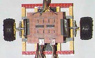
Stepper motor controller connection diagram (four-wire connection)
The ULN2003 / MC1413 is a 7-bit 50V 500mA TTL input NPN Darlington driver. This is sufficient to control a four-phase unipolar stepper motor, such as the KP4M4-001.
Latest Control Circuits Circuits
- Temperature-controlled fan
- Drain pump controller
- 3-volt high-volume buzzer
- Parking Assist
- Novel motor Y-△ control step-down starting circuit
- Easy to make light controlled delayed flash toy car
- A practical automatic electronic welcome circuit
- Homemade automatic replacement motorcycle horn
- What problems will be encountered when designing a constant temperature controller?
- Circuit diagram of the electronic bird singing sweetly
Popular Circuits
- Photoelectric tracking control circuit
- Three-phase stepper motor control circuit
- DC voltage stabilizing circuit and zero-crossing detection circuit in the indoor unit control circuit of Hisense KFR-25GW-06BP inverter air conditioner
- High-rise residential walkway lighting control circuit
- PLC light source robot hand bubble control circuit
- Relay control circuitb
- Intelligent iron control circuit
- Small power electric heater temperature detection control circuit
- audio signal control circuit
- Wide input range non-synchronous voltage mode control circuit


 京公网安备 11010802033920号