Voice controlled bird circuit
Source: InternetPublisher:newlandmark Keywords: Motor drive audio circuit voice-controlled bird circuit Updated: 2020/03/28
The voice-controlled bird is a simulated electronic craft. Its appearance is that of one or two birds with colorful feathers perched on a branch. Under voice control or manual switch operation, the bird can make a beautiful chirping sound. At the same time, the bird's body will also make movements such as swinging and flapping its wings, which is very interesting. In fact, these functions are accomplished by relying on the dedicated circuits in the base and the motor drive mechanism installed in the bird's body. The internal circuit of the voice-controlled bird has been measured and mapped, as shown in the attached figure.
In the picture, the main component IC is a special integrated circuit (using black paste soft packaging. There are eight pins in total. Pins ① and ④ are its working power input terminals. When the switch K installed on the machine base is pressed At this time, the bird singing program circuit stored in the IC will first output the audio signal from the IC pins ⑤ and ⑥ to the speaker (SPK) in a signal self-test mode. It will emit a pleasant bird chirping sound for about 20 seconds. At the same time, due to the internal There is also a special circuit that can sample, amplify, shape and convert the signal. The ② and ③ pins of Ic output a "low level" modulation signal to control the transistors Q2 and Q3, so that the C poles of Q2 and Q3 output drive The signal is sent to the two electrode sockets of "A bird" and "B bird". The driving voltage output from the socket is connected to the micro motor installed in the bird's body. This generates power; then through the deceleration and the transformation of the action lever mechanism, it drives The bird's head, wings and other parts move to produce very realistic effects.
When the chirping stops, the Ic② and ③ pins become "high level" output, so Q2 and Q3 are cut off, and the bird will no longer move after the motor loses power.
After this IC works for the first time, it then enters an extremely low power consumption "static standby" state. If you want to make Ic trigger work again, you need to input a trigger pulse again at the "trigger" function terminal of Ic⑦ pin.
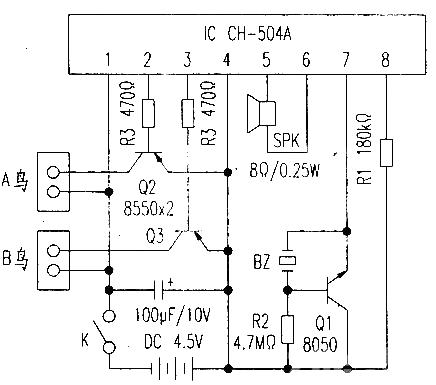
At the Ic⑦ pin, BZ, R2, and Q1 form a control trigger (voice control mode) functional circuit. The piezoelectric piece BZ is a sound sensing element. When BZ senses external sound, a weak induced voltage is generated on it. It is directly applied to the b and e junctions of Q1, amplified by Q1, and a pulse is output at the e pole of Q1 to the Ic⑦ pin. , and the Ic is triggered, and the Ic works again, allowing the birdsong and bird body movements to reappear. R2 on the voice control circuit sets the control sensitivity of the voice control. If its resistance is too large, the voice control sensitivity will be low: if the resistance of R2 is too small, the circuit will be overly "sensitive", resulting in too many Triggering will add noise.
Generally speaking, the failure rate of voice-controlled birds in normal use is very low. Failures often occur after a long time, due to corrosion on the battery poles under the machine base or on the "A and B bird" inserts that connect the birds. As a result, malfunctions occur. In this regard, you can use sandpaper and other tools to clean it and remove the rust. Then you can resume normal work.
- How to use the Arduino tone function to play a melody on a piezo buzzer or speaker
- Field effect tube amplifier circuit with beautiful sound
- Experiment of 2-in-1 single-ended Class A tube amplifier
- Two unique tube preamplifiers
- Sugon New Tube 2A3C Single-ended Tube Amplifier
- Converting a microphone preamplifier (RJ4558) into a headphone amplifier
- Preamplifier made of 6P15 tube
- 6C16+FU50 high-fidelity tube amplifier circuit with unique sound
- LMl876 is used to assist the audio power amplifier circuit
- 2W×2 power amplifier circuit using LM1877
- TDA2030 audio power amplifier circuit diagram
- Squelch Tuned Audio Switching/Mixing Circuit Diagram
- Typical audio signal control circuit diagram
- Robot sound generator
- Production and debugging of wireless FM microphone
- Homemade wireless audio repeater
- Design and production of wireless FM microphones
- Five-digit LED display audio power indication circuit diagram made with FD502
- Luminous and sound probe circuit diagram
- Torque motor driving welding electrode circuit


 京公网安备 11010802033920号