Overheat protection circuit schematic diagram
Source: InternetPublisher:笑流年 Keywords: thermistor battery power overheating protection ptc Updated: 2021/01/15
For continuously operating electromechanical equipment such as automatic lathes, electric ovens, and ball mills used in production, as well as other unattended equipment, accidents often occur due to motor overheating or thermostat failure, and corresponding security measures need to be taken. The PTC thermistor overheat protection circuit can conveniently and effectively prevent the above accidents.
Principle circuit
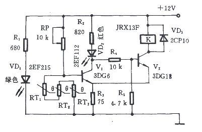
Taking the motor overheating protection as an example, it is a control circuit composed of a PTC thermistor and a Schmitt circuit. In the figure, RT1, RT2, and RT3 are three step-type PTC thermistors with consistent characteristics. They are buried in the windings of the motor stator. Under normal circumstances, PTC thermistors are at normal temperature and their total resistance value is less than 1KΩ. At this time, V1 is cut off, V2 is turned on, relay K is powered to close the normally open contact, and the motor is powered by the mains power supply.
When the motor locally overheats due to a fault, as long as one PTC thermistor is heated above the preset temperature, its resistance will exceed 10KΩ. So V1 is turned on, V2 is turned off, VD2 displays a red alarm, K is released when it loses power, and the motor stops running, achieving the purpose of protection.
Main component selection
The selection of PTC thermistor depends on the insulation level of the motor. The standard dimensions of the components are shown in the figure. The Curie temperature of the PTC thermistor is usually selected in a range that is about 40°C lower than the limit temperature corresponding to the motor insulation grade. For example, for a motor with Class B1 insulation, whose limit temperature is 130°C, a PTC thermistor with a Curie temperature of 90°C should be selected. (PTC thermistor for overheating protection)
The selection of relay K depends on the capacity of the motor. The one in Figure 2.3.1 is JRX-13F with a contact load of 0.5A, which is suitable for small motors. RP should choose a potentiometer with a locking mechanism.
Installation and commissioning
The recommended installation method is to bury the PTC thermistors in the windings of the motor stator. The debugging method is: place the PTC thermistor in a constant temperature box, set the temperature to TK, and adjust RP so that when the PTC thermistor is at TK-5℃, VD2 does not light up and K does not act; when TK+5℃, The VD2 light is on and K moves. Just lock the RP.
- Benefits of Wide Bandgap Technology for Power Converters
- Basic connection circuit of signal and power supply composed of ISOll3
- Single-power supply circuit for ISO122P/ISO124
- Op amp power supply decoupling bypass measures
- Principles and precautions of active discharge circuit
- How to use SBR to improve power conversion efficiency
- Charging control circuit made by solar energy
- 0.7~24V continuously adjustable current limiting power supply
- Car Audio Power Supply
- LM317T voltage regulation adjustable circuit diagram explanation
- Car battery charger circuit
- Radio power automatic shut-off circuit
- Mobile phone universal charger circuit diagram and working principle
- Power circuit b composed of intelligent thyristor modules
- PTC three-phase asynchronous motor protection circuit 5
- PTC three-phase asynchronous motor protection circuit four
- Delayed light circuit using relay (7)
- Positive Temperature Coefficient Thermistor Automotive Temperature Indicator
- Thermistor overload protection circuit
- Thermistor temperature measuring circuit


 京公网安备 11010802033920号