Choose a circuit design that matches your specific application
Source: InternetPublisher:明天见 Keywords: Power supply other power circuits Updated: 2021/06/11
Today's LED lighting has diverse applications, from simple incandescent or cold cathode fluorescent lamp (CCFL) replacements to new architectural, industrial, medical and other applications. In order to optimally match the lamp and light in the application, different LED lighting applications usually have corresponding performance standard requirements.
To drive LEDs, engineers can choose from a wide range of driver architectures. However, each architecture has its own advantages and disadvantages, and its adaptability to specific applications is better or worse. There are many factors to consider when selecting a driver architecture, with cost occupying the primary position, followed by isolation, dimming, flicker, color temperature, power factor, reliability, thermal management and other issues.
There are several basic LED driver architectures: secondary side control, primary side control, isolated/non-isolated. In addition, power factor control (PFC) is also a major performance consideration in many applications, with solutions consisting of two-stage or single-stage drives with PFC functionality, or single-stage drives without PFC functionality (mainly for low power applications). for 5W applications). Therefore, the entire driver subsystem is the result of a series of trade-offs to reduce bill of materials (BOM) costs and achieve maximum efficiency while providing dimming capabilities to create a temperature-controlled, fault-protected product.
Basic driver architecture
For optimal isolation and control, the secondary-side control architecture monitors the output voltage/current and provides feedback signals to the primary-side driver through an optically isolated path (Figure 1). This feedback signal enables the secondary-side controller to provide better current and voltage control accuracy. A simpler primary-side control scheme reduces system cost by eliminating the secondary-side controller and optically isolated signal paths, improving system performance while reducing system size. In this scheme, the primary-side driver determines the output current and voltage through primary-side waveform analysis (Figure 1). Depending on the quality of the analysis, primary-side control can match or exceed secondary-side regulation and performance, making it a common solution for today's isolated LED drivers.
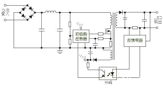
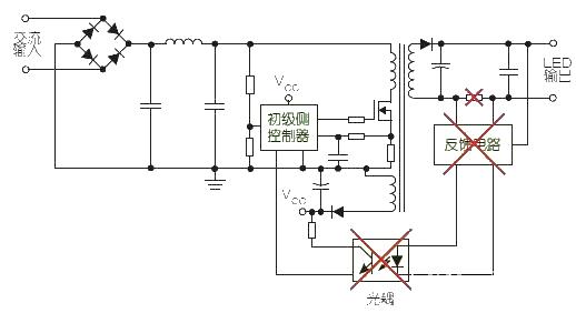
Figure 1: Two common LED driver solutions use secondary-side control (top) and primary-side control (bottom). Secondary-side control has better current and voltage control accuracy, but primary-side control can reduce component count and system size while improving performance.
The basic primary side control circuit is isolated via the output stage transformer. However, to reduce component costs, non-isolated solutions use inductors instead of transformers and can use buck controllers instead of primary-side driver flyback circuits (Figure 2). In the non-isolated scheme, the control mechanism is simplified, but the circuit requires more complex physical isolation to prevent short circuits between the input and output. Currently, most LED driver designs use an isolated architecture. Over the next year or two, advances in circuit design will provide opportunities to further reduce costs.
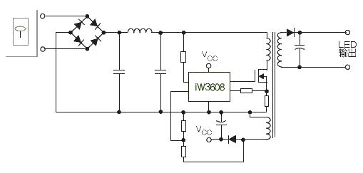
Figure 2: The primary-side driver can be designed in an isolated configuration by using a transformer in the output stage, or in a non-isolated configuration by using an inductor instead of the output transformer and a buck controller instead of the flyback circuit.
- How much current can a 2N3055 solar cell produce? How can I get 3055V from a 12N2 solar cell?
- A very convenient small power supply circuit to share
- Build a simple buck-boost regulator and test it on a breadboard
- 220V Remote Load Monitor
- INA155/INA156 is used to form a single-supply high-side current monitor for detecting load current
- Offline 8w LED Flyback Power Supply with PFC using NCP1014
- LED rechargeable flashlight circuit diagram
- A simple positive and negative power supply circuit
- Converting a lithium battery charging board into a constant voltage and current charger
- Adjustable voltage regulated power supply circuit
- Teach you a thyristor dimming LED drive power circuit design
- How to turn on the power with LLC controller?
- Take stock of wonderful designs
- Determining the prerequisites for successful circuit board design
- A design plan for a serial communication interface circuit
- Car glass hail melting circuit design
- An operational amplifier with very high amplification
- volumeter
- simple audio mixer
- Clock switching circuit and its precautions


 京公网安备 11010802033920号