Intelligent wireless network automotive test system hardware circuit design - circuit diagram read every day (84)
Source: InternetPublisher:三岁就很酷 Updated: 2020/04/20
Automobile testing is an important means to discover various problems in automobile design and development. Based on the test results, objective evaluation of various automobile performances can be made. As one of the basic projects of the automobile industry, automobile testing plays an important role in the overall development of the automobile industry. The automobile performance test system is a key component of the automobile test project. It is an organic whole composed of a number of interconnected and interacting sensors, instrumentation and other components to test the various performances of the automobile. The performance of the automobile test system Often have an important impact on the effectiveness of the entire vehicle test.
Overall system structure design
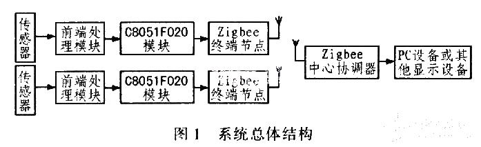
Automobile tests mainly include test items such as power performance, fuel economy, handling stability and emission characteristics. The main performance parameters include speed, acceleration, fuel consumption, temperature and dynamic motion parameters in the handling stability test, etc., which are obtained through sensors. The test signals of these parameters are processed by the front-end processing module (shaping, filtering, amplification, etc.) and then sent to the C805l-F020 microprocessor. After analog-to-digital conversion and data processing inside the microcontroller, the connection to the Zigbee terminal node is realized through the serial port. , and then the terminal node sends the data in the WLAN. After receiving the data, the Zi-gbee central node communicates with the host computer through the serial port. The central node can also send commands from the host computer to the terminal nodes to control the execution of the terminal nodes. The overall structure block diagram of the system is shown in Figure 1.
Front-end processing module
The sensor converts various common non-power signals into power signals, which are generally weak. The front-end processing module processes these signals and sends them to the A/D conversion port of the microcontroller. This system has a total of 8 sensor signals, including 2 voltage sensor signals, 2 -5~+5 V voltage signals, 2 4~20 mA current signals and 2 thermocouple signals for front-end processing. The front-end processing hardware circuits of the voltage sensor signal and thermocouple signal are shown in Figure 2 and Figure 3 respectively.
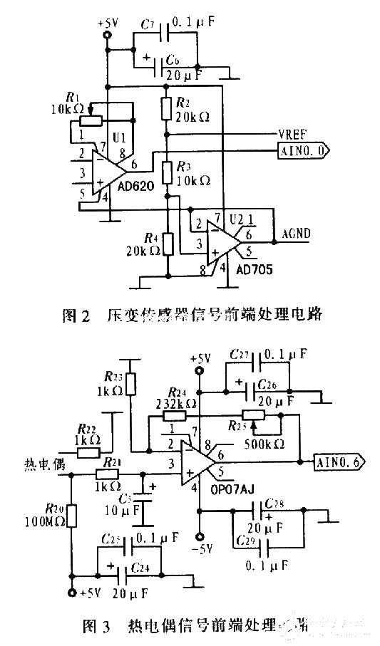
AD620 is a low-cost, high-precision instrumentation amplifier that requires only one external resistor to set the gain, with a gain range of 1 to 10,000. The front-end processing of the voltage sensor signal uses an amplifier circuit composed of AD62-0 and AD705. This part is powered by a single power supply. AD705 is a voltage follower that provides the zero point of the output voltage for AD620. Send VREF and AGND to the AINl of the 8-bit precision AD-Cl of the MCU. 0.AINl. 1 port, use the software program to calculate the reference voltage and analog ground of the signal. Thermocouple sensors are used to measure the temperature of key automotive components, and their front-end processing circuit uses the OP07 adjustable gain amplifier circuit. OP07 is a low-noise, non-chopper-stabilized bipolar operational amplifier integrated circuit with very low input offset voltage. The characteristics of low offset and high open-loop gain make OP07 particularly suitable for high-gain measurement equipment and amplified sensors. Weak signal etc. In situations where accuracy is not high, the offset voltage of OP07 can be ignored. In this circuit, R25 and R24 are used to adjust the system amplification. When selecting different types of thermocouples, the resistances of the two can be adjusted appropriately.
- Integrated soldering iron with protection function
- Water Softener
- A simple device activator circuit
- DIY an electromagnetic glove
- Share a solar beacon circuit
- Share an electronic touch organ circuit
- IoT-based pet feeder
- Share a fire sensor solution using MLX90640
- How to build an autonomous robot using the DonkeyCar platform
- Electronic fly killer
- How does an optocoupler work? Introduction to the working principle and function of optocoupler
- 8050 transistor pin diagram and functions
- What is the circuit diagram of a TV power supply and how to repair it?
- Analyze common refrigerator control circuit diagrams and easily understand the working principle of refrigerators
- Hemisphere induction cooker circuit diagram, what you want is here
- Circuit design of mobile phone anti-theft alarm system using C8051F330 - alarm circuit diagram | alarm circuit diagram
- Humidity controller circuit design using NAND gate CD4011-humidity sensitive circuit
- Electronic sound-imitating mouse repellent circuit design - consumer electronics circuit diagram
- Three-digit display capacitance test meter circuit module design - photoelectric display circuit
- Advertising lantern production circuit design - signal processing electronic circuit diagram


 京公网安备 11010802033920号