Power supply slow-start design in hot-swappable systems
Source: InternetPublisher:拳制龙 Keywords: Hot-swappable systems linear power supplies power supply filtering Updated: 2020/03/14
Generally speaking, using too many large-capacity capacitors on a circuit board is not helpful in filtering out high-frequency interference, especially when using a high-frequency switching power supply. Another problem is that too many large-capacity capacitors increase the impact on the power supply when powering on and hot-swapping circuit boards, which can easily cause problems such as power supply voltage drops, circuit board connector sparking, and slow voltage rise within the circuit board.
1. Hot-swappable systems must use power supply slow start design
In the hot-swappable system, the moment the board is inserted, the capacitor on the board starts charging. Because the voltage across the capacitor cannot suddenly change, it will cause the voltage of the entire system to drop instantly. At the same time, because the power supply impedance is very low, the charging current will be very large. Rapid charging will have an impact on the capacitors in the system, which can easily lead to the failure of tantalum capacitors. If a fuse is used for overcurrent protection in the system, the transient current may cause the fuse to blow. Choosing a high-current fuse may not blow when the system current is abnormal, and it will not provide protection. Therefore, in hot-swap systems, the power supply must adopt a slow-start design to limit the startup current to avoid excessive transient current from affecting system operation and device reliability.
LDO
1. In the design of step-down power supply with large voltage difference or large current, it is recommended to use switching power supply and avoid using LDO.
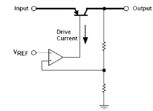
Using linear power supplies (including LDOs) can achieve lower noise, and because it is simple to use and low cost, it is widely used on single boards. The FPGA core power supply, the power supply for the RF clock portion of some circuit boards, etc. are all adjusted from higher voltage supplies using linear power supplies. LDO must calculate heat dissipation and meet derating specifications
2. When selecting the filter capacitor at the LDO output, pay attention to the minimum capacitance required in the manual and the ESR/ESL of the capacitor to ensure circuit stability. It is recommended to use multiple capacitors of equal value in parallel to increase reliability and improve performance.
The LDO output capacitor provides transient current for load changes. At the same time, because the output capacitor is in the voltage feedback regulation loop, in some LDOs, there are requirements for the capacitance to ensure the stability of the regulation loop. The capacitance of this capacitor does not meet the requirements, and the LDO may oscillate, causing large ripples in the output voltage.
Multiple capacitors in parallel, as well as large-capacity electrolytic capacitors in parallel with small-capacity ceramic capacitors, can help reduce ESR and ESL and improve the high-frequency performance of the circuit. However, for some linear regulated power supplies, the ESR of the output capacitor is too low. It may induce a decrease in the loop stability margin or even cause loop instability.
filter capacitor
1. Power supply filtering can use RC, LC, and π type filters. It is recommended that magnetic beads be preferred for power supply filtering, followed by inductors. At the same time, resistors, inductors and magnetic beads must consider the voltage drop caused by their resistance.
Plug in: Comparison of inductors and magnetic beads
2. Large-capacity capacitors should be used in parallel with small-capacity ceramic chip capacitors.
Large-capacity capacitors are generally electrolytic capacitors, which are larger in size and have longer leads. They are often wound structures (tantalum capacitors are sintered carbon powder and manganese dioxide). The equivalent series inductance of these capacitors is large, resulting in poor high-frequency characteristics of these capacitors, and the resonant frequency is approximately between a few hundred KHz and several MHz (see Sanyo company's OSCON device manual and AVX company's tantalum capacitor device manual). Small-capacity ceramic chip capacitors have low ESL and good frequency characteristics, and their resonance points can generally reach tens to hundreds of MHz (see the reference "High-speed Digital Design" and the ceramic capacitor device manuals of companies such as AVX). It can be used to provide a low-impedance return path for high-frequency signals and filter out high-frequency interference components on the signal. Therefore, when using large-capacity capacitors (electrolytic capacitors), small-capacity ceramic capacitors should be connected in parallel with the capacitor.
Large-capacity capacitors are generally electrolytic capacitors, which are larger in size and have longer leads. They are often wound structures (tantalum capacitors are sintered carbon powder and manganese dioxide). The equivalent series inductance of these capacitors is large, resulting in poor high-frequency characteristics of these capacitors, and the resonant frequency is approximately between a few hundred KHz and several MHz (see Sanyo company's OSCON device manual and AVX company's tantalum capacitor device manual). Small-capacity ceramic chip capacitors have low ESL and good frequency characteristics, and their resonance points can generally reach tens to hundreds of MHz (see the reference "High-speed Digital Design" and the ceramic capacitor device manuals of companies such as AVX). It can be used to provide a low-impedance return path for high-frequency signals and filter out high-frequency interference components on the signal. Therefore, when using large-capacity capacitors (electrolytic capacitors), small-capacity ceramic capacitors should be connected in parallel with the capacitor.
Methods to suppress peak current:
1. Take measures on the circuit board wiring to minimize the stray capacitance of the signal lines;
2. Another method is to try to reduce the internal resistance of the power supply so that the peak current does not cause excessive power supply voltage fluctuations;
3. The usual approach is to use decoupling capacitors for filtering, usually at the power inlet of the circuit board.
A 1uF~10uF decoupling capacitor filters out low-frequency noise; a 0.01uF~0.1uF decoupling capacitor (high-frequency filter capacitor) is placed between the power supply and ground of each active device in the circuit board for Filter out high frequency noise. The purpose of filtering is to filter out AC interference superimposed on the power supply, but the larger the capacitance used, the better, because the actual capacitor is not an ideal capacitor and does not have all the characteristics of an ideal capacitor.
The selection of decoupling capacitor can be calculated according to C=1/F, where F is the circuit frequency, that is, 0.1uF for 10MHz and 0.01uF for 100MHz. Generally, it can be 0.1~0.01uF.
The high-frequency filter capacitor placed next to the active device has two functions. One is to filter out the high-frequency interference transmitted along the power supply, and the other is to promptly supplement the peak current required when the device operates at high speed. Therefore, the placement of the capacitor needs to be considered.
Due to the existence of parasitic parameters, the actual capacitor can be equivalent to the resistance and inductance connected in series on the capacitor, which are called equivalent series resistance (ESR) and equivalent series inductance (ESL). In this way, the actual capacitor is a series resonant circuit, and its resonant frequency is:
The actual capacitor is capacitive at frequencies below Fr and inductive at frequencies above Fr, so the capacitor is more like a band-stop filter.
Due to its large ESL and Fr less than 1MHz, the 10uF electrolytic capacitor has a good filtering effect on low-frequency noise such as 50Hz, but has no effect on high-frequency switching noise of hundreds of megahertz.
The ESR and ESL of a capacitor are determined by the structure of the capacitor and the dielectric used, not the capacitance. The ability to suppress high-frequency interference cannot be improved by using a larger-capacity capacitor. For the same type of capacitor, at a frequency lower than Fr, the impedance of the large-capacity capacitor is smaller than that of the small-capacity capacitor. However, if the frequency is higher than Fr, ESL determines There will be no difference in impedance between the two.
Using too many large-capacity capacitors on the circuit board is not helpful in filtering out high-frequency interference, especially when using a high-frequency switching power supply. Another problem is that too many large-capacity capacitors increase the impact on the power supply when powering on and hot-swapping circuit boards, which can easily cause problems such as power supply voltage drops, circuit board connector sparking, and slow voltage rise within the circuit board.
1. Comparison between inductors and magnetic beads
Inductors and magnetic beads have many similarities in appearance and function, and in many cases, magnetic beads and inductors can replace each other, but they are not completely equivalent.
The difference between the two:
(1) Although both inductors and magnetic beads can filter, their mechanisms are different. Inductor filtering converts electrical energy into magnetic energy. Magnetic energy affects the circuit in two ways: one way is to exchange electrical energy again, which appears as noise; the other way is to radiate outward, which appears as EMI (Electro-Magnetic Interference) electromagnetic interference. Magnetic beads convert electrical energy into thermal energy and will not cause secondary interference to the circuit.
(2) The inductor has good filtering performance in the low frequency band, but the filtering performance above 50MHz is poor; the magnetic beads can fully absorb high-frequency noise by using its resistance and convert it into heat energy to completely eliminate high-frequency noise. .
(3) From the perspective of EMC (Electro Magnetic Compatibility), because magnetic beads can convert high-frequency noise into heat energy, they have very good radiation resistance and are commonly used anti-EMI devices, often used in user interface signals. Line filtering, power supply filtering of high-speed clock devices on single boards, etc.
(4) When an inductor and a capacitor form a low-pass filter, since the inductor and capacitor are both energy storage devices, their cooperation may produce self-excitation; magnetic beads are energy-consuming devices, and when working together with the capacitor, no self-excitation will occur. Excited.
(5) The rated current of the power supply inductor is relatively large. Therefore, the inductor is often used in power supply circuits that require large currents, such as for power module filtering; while magnetic beads are generally used for chip-level power supply filtering.
- +5V power supply for charge pump battery charger
- 500W MOSFET power inverter 12V to 110V/220V
- Simple lithium-ion/lithium polymer battery charger
- Fluorescent lamp inverter
- Dual USB charger with switching regulator
- USB-powered lithium-ion battery charger
- Simplifying 100V Input Wide VIN Power Conversion
- A flyback converter solution where two outputs are better than one
- Mitigating Overheating in Hyperscale and Ultra-Scale FPGA Applications
- Top Three Ways to Split Voltage Rails into Bipolar Power Supplies
- Diamond differential input power amplifier power circuit
- Super Class A power amplifier power circuit
- Low voltage adjustable reference power circuit
- Household emergency power circuit 02
- Household emergency power circuit
- Remote control TV doorbell power circuit
- Common power circuits and applications 09
- Common power circuits and applications 01
- AC-DC conversion power supply-inverter power supply circuit
- 5V uninterruptible power supply circuit


 京公网安备 11010802033920号