Siren signal generator circuit
Source: InternetPublisher:闪电杰克 Keywords: signal generator generator circuit oscillator pulse Updated: 2021/01/08

Siren signal generator circuit
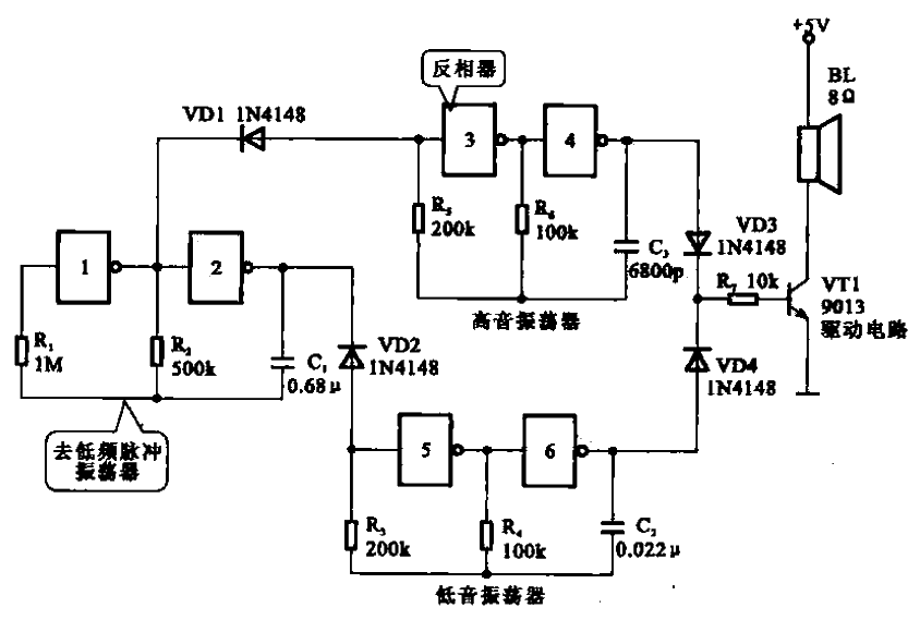
Shown is a siren signal generator circuit consisting of a six-inverter integrated circuit CD4069 . Inverters 1 and 2 form an
ultra-low frequency pulse oscillator , and NOT gates 3 and 4 form a high-frequency oscillator. NOT gates 5 and 6 form a bass oscillator. The output of the ultra-low frequency pulse
oscillator
controls the high and low frequency oscillators to oscillate in turn through the diodes VDI and VD2. The oscillation signals are
amplified by the semiconductor transistor VT1 through VD3 and VD4 respectively, and then drive the siren sound from the speaker.
- Analysis of the flow direction of transistor current
- What does a rectifier do? What is the process of rectification?
- In-depth analysis of energy losses in oscillation frequencies
- What types of power field effect tubes are there? Selection criteria for power field effect tubes
- Simple Wired Spy Bug Circuit Built Based on IC741
- What is a Demultiplexer
- What is the difference between high-side and low-side resistive current sensing
- Using an Op Amp to Drive a Simple and Practical Power Amplifier
- Purpose and composition of amplifier circuit: low frequency voltage amplifier amplifier circuit
- Circuit diagram of a differential amplifier circuit
- Do you know about the new RF vector signal generator?
- Various signal generator circuits
- square wave generator circuit
- One-digit display timer circuit diagram
- Tone generator circuit
- Triangular wave signal generator circuit composed of LM359
- Single stage sound signal generator circuit
- Pulse, triangle wave and sawtooth wave signal generator circuit using 566 02
- 88 to 108MHz FM signal generator circuit
- Two examples of 60Hz time base signal generator circuit circuit-a


 京公网安备 11010802033920号