What does a rectifier do? What is the process of rectification?
Source: InternetPublisher:念慈菴 Keywords: Rectifier Updated: 2025/01/24
Some say that the history of power electronics began in 1902 with the invention of the pool cathode glass bulb mercury arc rectifier. The credit for this revolutionary nonlinear component goes to an American inventor named Peter Cooper Hewitt. He discovered the phenomenon while experimenting with mercury vapor lamps, which he patented in 1901. Through his experiments, he found that the current only flows in one direction, from the anode to the cathode, and therefore has a rectifying effect.
The invention of the mercury arc rectifier paved the way for many electronic devices that are an integral part of our daily lives and work. No wonder some people consider its invention to be the beginning of the classic era of power electronics.
1. What is a rectifier?
By definition, a rectifier is an electrical device that converts alternating current, which intermittently reverses direction, into direct current, which flows in only one direction. A rectifier is a component of an electrical circuit that allows current to flow in one direction while blocking it from flowing in the other direction. In terms of applications, rectifiers can be found in typical benchtop power supply units.
The rectification process itself involves a device that allows electrons to flow in only one direction. As you can see, it is very similar to the function of certain semiconductor components. Moreover, the most basic rectification circuit is the half-wave rectifier. However, physically, rectifiers can take many forms, including mercury arc valves, semiconductor diodes, vacuum tube diodes, and even wet chemical cells, to name a few.

As shown in the figure above, this is a simple half-wave rectifier. A typical use of the rectifier is in a benchtop power supply unit.
2. Rectifier Application
In terms of applications, rectifiers have countless uses. However, they are often used as components in DC power supplies or HVDC transmission systems. The rectification process also has a variety of applications. For example, it can be used as a radio signal detector, or a flame presence detector in gas heating systems.
Furthermore, depending on the type of AC power source and the arrangement of the rectifier circuit, the output of the rectifier may need to be further smoothed to produce an output (voltage) that is both uniform and stable. Most rectifier applications require a stable and constant DC voltage, i.e. powering PCs, TVs, and motors. Therefore, to meet these requirements, rectifier designs employ electronic filters to smooth the output of the rectifier.
Generally speaking, these electronic filters can be a capacitor, a bank of capacitors, a choke, or a choke and resistor, usually followed by a voltage regulator to produce a stable voltage.
3. Types of rectifiers and rectifier circuits
Before the use of silicon semiconductor rectifiers, there were copper oxide-based and selenium-based metal rectifier stacks, as well as vacuum tube thermionic diodes. However, with the rise of semiconductor electronic technology, the elimination of vacuum tube rectifiers is inevitable. For example, today, there are various types of semiconductor diodes.
When simple rectification is not enough, other devices come into use where the output voltage is variable. Of course, these other devices are also capable of controlling the electrodes and providing unidirectional current. Again, these types of high power rectifiers are used for high voltage DC power transmission, and they contain various types of silicon semiconductor devices.
Typically, these types of rectifiers are called thyristors. These and other controlled switching solid-state switches effectively act as diodes, passing current in one direction only.
In general, rectifier circuits can be multi-phase or single-phase, but most small-power rectifiers used in household appliances are single-phase. In addition, three-phase rectification is essential in industrial applications and high-voltage DC transmission.
4. Single-phase rectifier and half-wave rectifier
In the case of a single-phase power supply with half-wave rectification, only half of the AC wave will pass through, while it blocks the other half, regardless of polarity. Since only half of the input waveform reaches the output, this translates into a lower output voltage. In addition, half-wave rectification requires a single diode in single-phase power and three diodes in three-phase power.
Typically, the DC output produced by a rectifier is both unidirectional and pulsating. A half-wave rectifier produces more ripple than a full-wave rectifier. Of course, this means that it requires more filtering to remove the harmonics of the AC frequency from its output.
5. Single-phase rectifier and full-wave rectifier
A full-wave rectifier converts the entire input waveform into a single and constant polarity output (positive or negative). Full-wave rectification converts both polarities of the input waveform into pulsating DC, producing a higher output voltage.
In terms of design, you can create a full-wave rectifier with four diodes in a bridge configuration or two diodes and a center-tapped transformer and an AC source that can be a transformer without a center tap. For example, a single-phase AC source with a center-tapped transformer and two back-to-back diodes (anode to anode or cathode to cathode) can form a full-wave rectifier. Although it requires twice the number of transformer secondary turns to produce an equal output voltage compared to a bridge rectifier, its power rating is still not affected.
6. Multiphase Rectifier
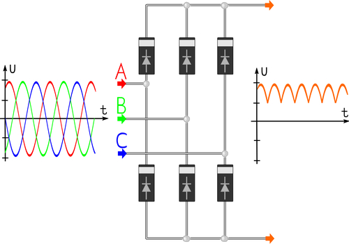
Single-phase rectifiers are commonly used in power supplies for household appliances. In contrast, high-power and industrial applications generally use multiphase rectifiers. Like single-phase rectifiers, three-phase rectifiers can also be in the form of half-wave circuits, full-wave bridge circuits, or full-wave circuits using center-tapped transformers.
You can often find thyristors used instead of diodes for voltage output regulation. Also, most devices that provide DC also produce three-phase AC. An example is a car alternator that contains six diodes that act as a full-wave rectifier to charge the car battery.
Note: A thyristor is a solid-state semiconductor device with four layers of alternating P-type and N-type materials. Also, it acts only as a bistable switch, turning on when the gate receives a current trigger, and stopping conducting as the voltage is removed. Also, the removal method is usually through reverse bias, but it can be through other means.
There are many devices today that owe their functionality to so-called rectifiers, both in single-phase and multi-phase configurations, and devices such as televisions and even PCs would not be possible. Although its invention dates back to the early 20th century, without rectifiers our present would look very different.
- How do pull-up resistors work? How do I choose a pull-up resistor value?
- Symbol/working principle/type/characteristics/application scenarios of depletion-mode MOSFET
- Causes and solutions for noise in digital Class D amplifiers
- Analysis of the working principle of CMOS/CCD image sensor
- Transfer characteristics of BJT, how to apply Shockley equation?
- Datasheet/Pinout/Technical Specifications of LMC555
- Working principle/advantages/disadvantages/size of optical fiber
- Analysis of three simple electronic dice circuits
- Why use PWM? What are its advantages?
- Build a musical fountain using Arduino and sound sensor
- Vishay FRED Pt® ultra-fast recovery rectifier launched on the market
- Three-phase CZ-320 silicon rectifier DC welding machine no-load automatic stop circuit
- Three-phase rectifier intelligent control module internal wiring
- KT04 type is used in three-phase fully controlled bridge rectifier and speed regulation circuit
- Single tube rectifier energy consumption brake control circuit
- Music doorbell circuit with two triggering methods
- Energy-saving multipurpose electronic rectifier circuit
- SXZl three-phase rectifier (closed loop) trigger board typical application circuit
- GCA 20A/110V silicon rectifier, filling and welding dual-purpose machine circuit
- Zero type rectifier and voltage stabilizing circuit


 京公网安备 11010802033920号