Minor changes to the OLYMPUS CLE-10 cold light source startup circuit
Source: InternetPublisher:难得正经 Keywords: Protection Circuit Updated: 2025/05/06
The OLYMPUSCLE-10 cold light source often burns out the bulb at the moment of turning on, resulting in high cost of use. The main reason is that the bulb (150W/15V) has a resistance of about 1.5Ω at rated power, and a very small resistance (<0.05Ω) in the cold state. Therefore, a large surge current will be generated at the moment of lighting, burning out the filament or the connection between the filament and the pin. In order to eliminate the surge current at the moment of turning on and increase the service life of the bulb, an improved circuit is designed. After use, the effect is good and the phenomenon of the bulb burning out at the moment of starting is completely eliminated. The circuit and production method are introduced as follows:
1. Working principle of the bulb start-up delay protection circuit
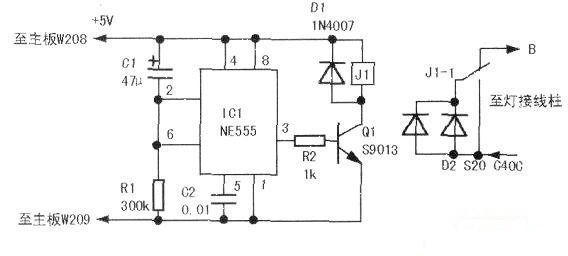
The bulb of this machine adopts AC power supply from a high-power power transformer. When working normally, the voltage at the bulb end is about 15.6V (it will change with the change of the mains voltage). I imagine that if a diode can be connected when the bulb starts, the power supply voltage of the bulb can be changed to half-wave rectification, and the voltage is about 15.6V×0.45=7V. At this time, the current is reduced by more than 50% compared with the original circuit. After a delay of 10 to 20 seconds, the filament is preheated, and the resistance increases rapidly. Then the diode is disconnected, and the bulb enters a normal working state, so as to achieve the function of bulb start-up delay protection. The figure below is the designed improved circuit, which is based on NE555 and constitutes a typical delay conduction circuit. The working principle is as follows: after turning on the host power switch, since the voltage on C1 cannot change suddenly, it can be regarded as a short circuit, then IC1②, ⑥ feet are at high potential, making ③ foot output low level, Ql cut off, Jl does not work, at this time the bulb current is started through the Jl-l normally closed contact and the diode to achieve step-down, at the same time C1 starts to charge through Rll0, IC1②, ⑥ terminal voltage gradually decreases, when IC1② foot is 1/3VDD voltage, IC1 is set, ③ foot outputs high level, Q1 is saturated and turned on, Jl is attracted, the diode is short-circuited by the J1-1 normally open contact, and 15.6V AC power directly powers the bulb.
The delay time of this circuit is determined by Cl and Rl. The delay time is approximately td=l.lRl×Cl, and the design parameters are approximately 15.5 seconds.
2. Selection of circuit component parameters and their production
This circuit has few components, and the main component parameter requirements are as follows: Cl leakage current should be small; Jl uses 5VDC power supply, and the contact current should be greater than 10A; D2 requires a withstand voltage of >40V and a working current of >15A. The author uses S20C40, which is commonly used in the power supply of scrapped computer host, and uses two diodes in parallel. Due to the short working time, no heat sink is required; there are no special requirements for other components. All components are welded on a 4×3cm universal circuit board, and the circuit does not need to be debugged. The circuit board can be fixed next to the terminal inside the machine.
- Real drawing of electric mosquito swatter circuit diagram
- Homemade Ultrasonic Atomizer
- Range hood automatic control circuit
- S-Video/PAL Video Converter
- Share a home telephone recorder circuit diagram
- Electric oven temperature controller circuit diagram
- Integrated circuit sampling amplification circuit diagram
- DC detection automatic watering controller circuit
- Northern brand BD-90 refrigerator circuit
- Universal inverter external knob forward control
- Overload protection circuit
- Capacitive Neutral Leakage Protection Circuit
- Comprehensive protection circuit for transformer
- Three-phase motor overcurrent protection circuit
- Three-phase motor phase failure transistor protection circuit
- Three-phase power supply phase failure protection circuit
- Motor waterproof protection circuit
- Mains undervoltage and overvoltage protection circuit 4
- Generator longitudinal differential protection circuit a
- Diesel generator speed protection circuit


 京公网安备 11010802033920号