Simple and practical experimental water softening circuit
Source: InternetPublisher:酷到被通缉 Keywords: Water Softening Updated: 2025/05/16
As people's living standards improve, the standards for drinking water have also increased. This circuit can provide high drinking water standards and can verify the effect of magnetized water through experiments.
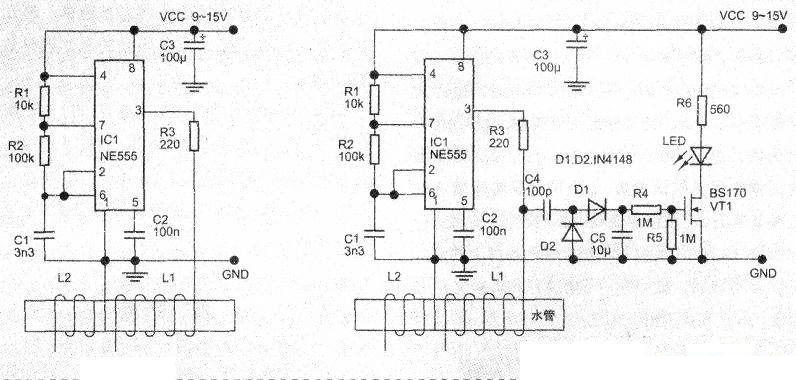
The circuit is shown in the left and right figures below. Under the action of the magnetic field or electric field, small calcium carbonate crystals in the water condense and form large crystals, which can effectively weaken the calcium carbonate deposition and avoid the condensation of scale on the walls of water pipes, the bottom of kettles, etc. There is no convincing theoretical explanation for the phenomenon that the calcium carbonate deposition process in water is weakened by the magnetic field or electric field.
There are two ways to achieve this. One is to place the water supply pipe in a strong magnetic field of a permanent magnet. The magnetic field strength must be greater than 2.5G. The permanent magnet can be a magnet similar to that on a high-power speaker. The other method is to use electromagnetic methods. The circuit on the left below is an example.
ICl (NE555) is connected to a multivibrator, and the output square wave frequency is about 15kHz and the amplitude is 15V. The signal is added to the water supply pipe through two open-circuit coils, generating an alternating electromagnetic field near the water supply pipe.
The coils must be well insulated. L1 and L2 are made of 1mm diameter insulated wires, each tightly wound 100 times on the plastic water pipe. Remember that the two coils must be open-circuited. The two coils are 5cm apart.
The circuit on the right is a supplement to the circuit on the left. It adds a working indicator light. The working indicator light does not use a simple LED to indicate the on and off of the power supply, but rectifies the 15kHz square wave signal output by ICl (NE555) to control the conduction of the field effect tube VT1, so that the LED tube D3 emits light. In this way, D3 will only emit light when the oscillation signal exists. The power supply can be a battery or a small voltage-stabilized power supply, and the working voltage can be 9 to 15V. The parameters of each component are marked in the figure. There are no special requirements, and general components can be used.
- Ultrasonic humidifier (ultrasonic atomizer)
- Principle and analysis of infrared automatic hand washing machine designed by LM567
- Detailed explanation of hifi headphone amplifier circuit diagram
- How to use BME680 to design a smart home control center
- Satellite TV room-to-room reception
- Using CD4017 to form an analog pendulum circuit
- cooking timer circuit
- Circuit diagram of Rongsheng CFXB1, 3 and 4 double lamp thermal insulation automatic rice cooker
- Lihe ESA-25 temperature-adjustable electronic crock circuit diagram
- AV switch made with decoder
- Car voice cell phone call reminder circuit diagram
- Car mobile phone charger circuit diagram
- Practical circuit diagram that enables remote wake-up/shutdown
- Cell phone detector circuit diagram
- Key debounce circuit diagram
- Philips shaver circuit diagram
- Design and production circuit diagram of wireless FM microphone
- AD7780 electronic scale circuit diagram
- Illustration of the design principles and applications of mobile phone radio frequency circuits
- Wireless frequency modulation (FM) microphone circuit diagram using Q5337


 京公网安备 11010802033920号