Production of Power Line Carrier Remote Control Alarm
Source: InternetPublisher:偷熊计划 Keywords: Alarm Updated: 2024/10/09
Power line carrier remote control is particularly suitable for home use because it does not require additional wiring or occupy radio frequencies. Here we introduce a simple and easy-to-make power line carrier remote control alarm, which may bring some convenience to your life.
Working Principle Transmitter (see Figure 1): The transmitter consists of Q1 and Q2 connected in a composite tube to form a Hartley oscillator with a frequency of 135KHz. The power supply with a voltage of 30V is composed of C2, D1, D2, D3, C5, etc. When the transmitter button P1 is pressed, the 135KHz oscillation signal induced in the auxiliary transformer of L1 is injected into the power line network through C1.
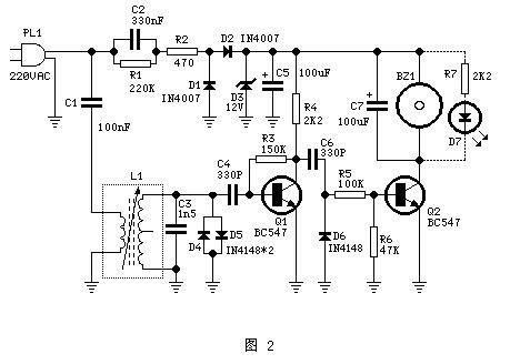
Receiving part (see Figure 2): The 135KHz sine wave from the transmitting part is transmitted through the power line to the receiving part, and the 135KHz signal is taken out through the frequency selection circuit composed of C1, L1 and C3. The signal is amplified by Q1 and shaped into a square wave signal with an amplitude of 12V. D4 and D5 constitute a limiting circuit to ensure that the base peak voltage of Q1 is less than 1V to prevent various abnormal interference pulses in the power line network from damaging Q1. The role of D6 is to filter out the negative polarity part of the signal, and Q2 drives the alarm part to work. C7 is used here to keep the output part stable and filter out the residual part of the signal. The 12V power supply part is composed of C2, D1, D2, D3, C5, etc.

Key points for production and debugging
1. During debugging, the magnetic core of the transmitting and receiving parts L1 needs to be carefully adjusted to ensure the maximum output at both ends of C3 of the transmitting and receiving parts.
2. If conditions permit, it is best to use an oscilloscope to observe the waveforms transmitted and received by each other during debugging at a distance.
3. If L1 uses the intermediate frequency of a 455KHz medium wave radio, an output frequency of about 135KHz should be obtained when all the magnetic cores are adjusted to the lowest position.
4. If other L1 with similar resonant frequency is used, C3 of the transmitting and receiving parts must be adjusted at the same time, generally 1~3.3nF.
5. The output part can be a buzzer or LED or both. If only LED is used, R7 can be changed to 1K to increase its brightness. An LED with a diameter of 10mm can be used.
6. When selecting components, please note that the withstand voltage of C1 and C2 of the transmitting and receiving parts must be greater than 400V. L1 can use the intermediate frequency used in general medium wave radios. If there are no special requirements for other components, refer to Figures 1 and 2 for selection.
7. Since the circuit part is directly connected to the 220-volt power supply, special attention should be paid during debugging to avoid direct contact with the circuit part. Before the device is put into use, the circuit part should be placed in a reliably insulated plastic box and ensure safety and reliability before use.
- How to use a microcontroller to control a servo motor?
- Servo motor pin diagram/working principle/application
- What are the challenges in designing a permanent magnet linear generator?
- DC motor drive circuit composed of L293D
- Working principle of ZNB-S digital display intelligent motor protector control circuit
- One-way rotation circuit of motor controlled by contactor
- Design and principle analysis of practical electric curtain remote control device
- Design and production of no-load automatic power-off device for household power supply
- PIC microcontroller controlled remote anti-theft alarm circuit
- A novel and practical power line anti-theft and cutting alarm circuit
- multi-tone alarm
- LM3911 (alarm and automatic control equipment) single-chip temperature control circuit
- Differential voltage or differential current alarm
- Combustible gas leakage degree display alarm (2)
- Instrumental moisture alarm
- Soil moisture upper and lower limit alarm
- rain alarm
- Conference speech time limit alarm
- Boiler water level alarm
- Blackout alarm


 京公网安备 11010802033920号