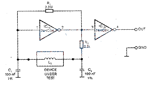
A low-cost inductance meter consisting of a single IC
Source: InternetPublisher:zht24 Keywords: 74HC04 inductance test circuit Updated: 2024/07/23
This Design Idea shows how to build a reliable, low-cost, simple inductance meter. The basis of the inductance meter is a Pierce CMOS buffered oscillator (see Figure). Instead of an ordinary quartz crystal, it is connected to the inductor to be measured. This oscillator uses a simple CMOS inverter biased by resistor R1 in its linear region to form a high-gain inverting amplifier. Because of this high gain, the inverter consumes less power than an unbuffered gate, even when driving the output high and low with small signals.
The Lc network forms a parallel resonator. Its resonant frequency fo=1/2π√LxCs. This frequency corresponds to the period T0, where CS=C1||C2=50nF. Therefore, the resonant frequency f0 or the period T0 can be measured to calculate the inductance LX. At the resonant frequency, the Lc network provides a 180° phase shift from input to output. The phase shift of the oscillator's oscillation loop f0 must be 360°. And the gain of the oscillation loop must be greater than 1 in order to generate oscillation. The inverter provides an additional 180° phase shift from input to output and a high gain to compensate for the attenuation of the network.
The value of resistor R1 can reach 1MΩ~10MΩ. Resistor R2 isolates the output of LC network Ic1A. A clean square wave can be obtained from the gate output. In addition, R2 can also increase the phase shift of the resonant frequency to improve frequency stability. In order to achieve the best performance, low self-inductance film capacitors can be used, such as Vishay's MKP1837 polypropylene film capacitor series, with an accuracy of up to 1%. Standard tolerance film capacitors can be used, and the capacitance can be selected with a precision capacitance tester to achieve the best accuracy. The circuit has low power consumption and can use batteries as a power source.

- How to test whether the multimeter is working properly
- Balcony intelligent invisible anti-theft net
- DIY Multimeter High Frequency Signal Probe
- Bat sound detection circuit
- System display circuit of electric bicycle speed and odometer composed of CD4076 and 74LS138
- Simple electric tachometer
- Four logic probe circuit diagrams
- DT8 type 5A current mutual induction three-phase four-wire active energy meter wiring
- High resistance DC differential amplifier circuit
- Numerical control following or inverting circuit
- Machine tool maintenance bearing fault detection circuit
- Towel machine fault detection circuit
- Three-phase power supply phase sequence detection circuit
- A5349 type AC smoke detection circuit - block diagram
- Underwater acoustic sensor detection circuit
- Light detection circuit
- Telephone ringing detection circuit
- Film thickness detection circuit using eddy current method
- Light sensor particle size distribution detection circuit
- Infrared two-dimensional temperature distribution detection circuit


 京公网安备 11010802033920号