KEMET Part Number: C315C220J5G5TA
GoldMax 300 Comm C0G, Ceramic, 22 pF, 5%, 50 VDC, C0G, GoldMax, Commercial Standard, Lead Spacing = 2.54mm
General Information
Supplier:
Series:
Style:
Description:
RoHS:
Termination:
Failure Rate:
Halogen Free:
KEMET
GoldMax 300 Comm C0G
Radial
GoldMax, Commercial Standard
Yes
Tin
N/A
Yes
Specifications
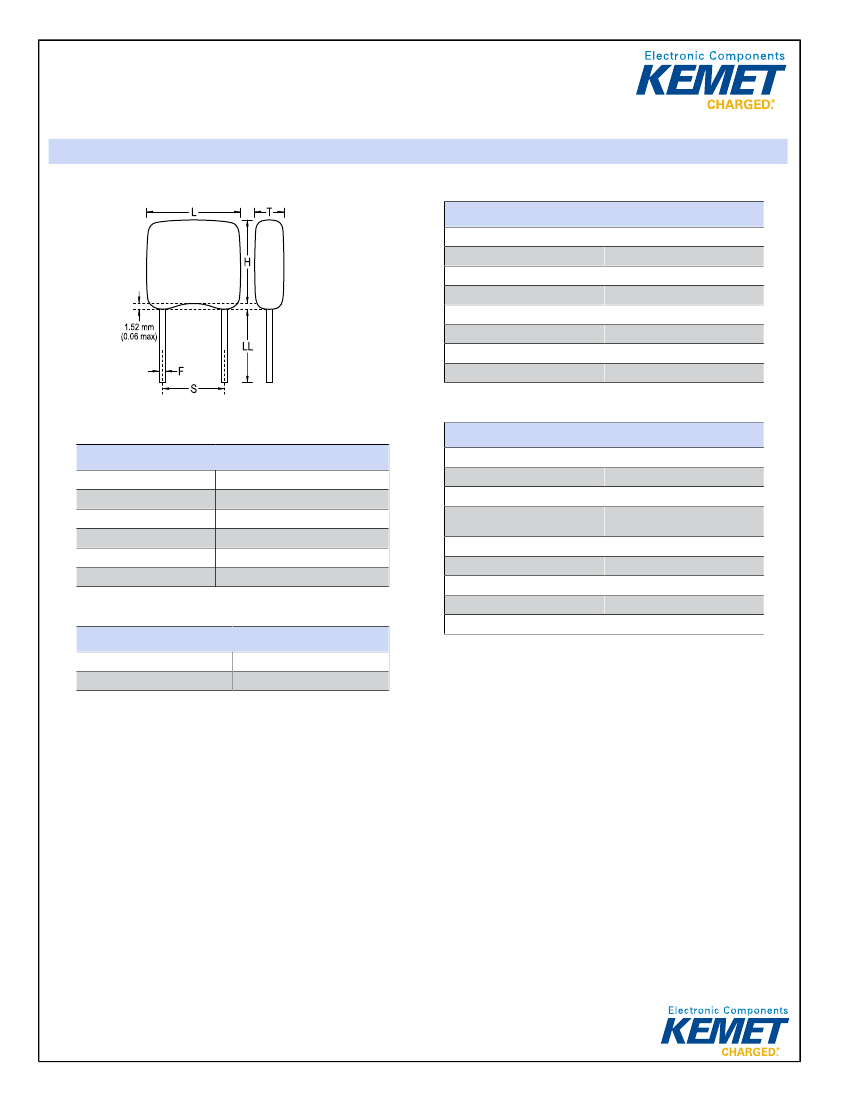
Dimensions
L
H
T
S
LL
F
3.81mm MAX
3.14mm MAX
2.54mm MAX
2.54mm +/-0.78mm
7mm MIN
0.51mm +0.1/-0.025mm
Capacitance:
Capacitance Tolerance:
Voltage DC:
Dielectric Withstanding
Voltage:
Temperature Range:
Temperature Coefficient:
Dissipation Factor:
Aging Rate:
Insulation Resistance:
22 pF
5%
50 VDC
125 V
-55/+125C
C0G
0.10% 25C
0% Loss/Decade Hour
100 GOhms
Packaging Specifications
Packaging:
Packaging Quantity:
Bulk, Bag
500
Statements of suitability for certain applications are based on our knowledge of typical operating conditions for such applications, but are not intended to constitute - and
we specifically disclaim - any warranty concerning suitability for a specific customer application or use. This Information is intended for use only by customers who have the
requisite experience and capability to determine the correct products for their application. Any technical advice inferred from this Information or otherwise provided by us
with reference to the use of our products is given gratis, and we assume no obligation or liability for the advice given or results obtained.
Generated 10/03/2018 - bb8bee12-505f-42d0-b3f0-588bd83411c6
© 2006 - 2018 KEMET
 京公网安备 11010802033920号


