
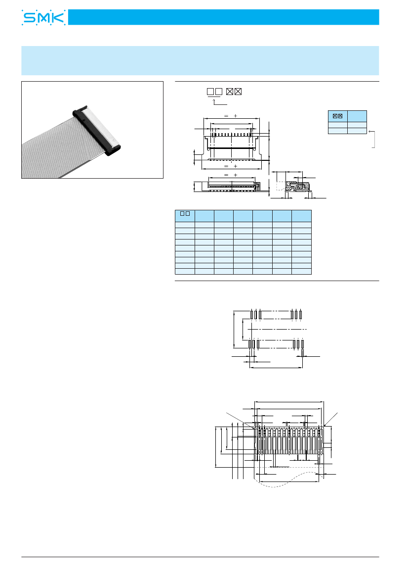
Card Edge Connector, 65 Contact(s), 1 Row(s), Female, Right Angle, 0.012 inch Pitch, Surface Mount Terminal, Locking, Natural Insulator,
| Parameter Name | Attribute value |
| Is it lead-free? | Lead free |
| Maker | SMK |
| Reach Compliance Code | unknown |
| ECCN code | EAR99 |
| Is Samacsys | N |
| Other features | ZIF, LOW PROFILE |
| body width | 0.071 inch |
| subject depth | 0.195 inch |
| body length | 0.882 inch |
| Connector type | FFC/FPC CONNECTOR |
| Contact to complete cooperation | GOLD |
| Contact completed and terminated | GOLD |
| Contact point gender | FEMALE |
| Contact material | COPPER ALLOY |
| contact mode | RECTANGULAR |
| Contact resistance | 30 mΩ |
| Contact style | BELLOWED TYPE |
| DIN compliance | NO |
| Dielectric withstand voltage | 100VAC V |
| Filter function | NO |
| IEC compliance | NO |
| maximum insertion force | ZIF N |
| Insulation resistance | 100000000 Ω |
| Insulator color | NATURAL |
| insulator material | THERMOPLASTIC |
| JESD-609 code | e4 |
| MIL compliance | NO |
| Plug contact pitch | 0.012 inch |
| Mixed contacts | NO |
| Installation option 1 | LOCKING |
| Installation method | RIGHT ANGLE |
| Installation type | BOARD |
| PCB row number | 2 |
| Number of rows loaded | 1 |
| Maximum operating temperature | 85 °C |
| Minimum operating temperature | -40 °C |
| Options | GENERAL PURPOSE |
| PCB contact pattern | STAGGERED |
| PCB contact row spacing | 4.2418 mm |
| Rated current (signal) | 0.3 A |
| reliability | COMMERCIAL |
| Terminal pitch | 0.3 mm |
| Termination type | SURFACE MOUNT |
| Total number of contacts | 65 |
| UL Flammability Code | 94V-0 |
| Evacuation force-minimum value | ZIF N |
| Base Number Matches | 1 |
| CFP7565-0250F | CFP7539-0350F | CFP7551-0350F | CFP7557-0350F | CFP7565-0350F | CFP7580-1601F | CFP7584-1601F | |
|---|---|---|---|---|---|---|---|
| Description | Card Edge Connector, 65 Contact(s), 1 Row(s), Female, Right Angle, 0.012 inch Pitch, Surface Mount Terminal, Locking, Natural Insulator, | Card Edge Connector, 39 Contact(s), 1 Row(s), Female, Right Angle, 0.012 inch Pitch, Surface Mount Terminal, Locking, Natural Insulator, | Card Edge Connector, 51 Contact(s), 1 Row(s), Female, Right Angle, 0.012 inch Pitch, Surface Mount Terminal, Locking, Natural Insulator, | Card Edge Connector, 57 Contact(s), 1 Row(s), Female, Right Angle, 0.012 inch Pitch, Surface Mount Terminal, Locking, Natural Insulator, | Card Edge Connector, 65 Contact(s), 1 Row(s), Female, Right Angle, 0.012 inch Pitch, Surface Mount Terminal, Locking, Natural Insulator, | Card Edge Connector, 80 Contact(s), 1 Row(s), Female, Right Angle, Surface Mount Terminal, | Card Edge Connector, 84 Contact(s), 1 Row(s), Female, Right Angle, Surface Mount Terminal, |
| Reach Compliance Code | unknown | unknown | unknown | unknown | unknown | unknown | unknown |
| Other features | ZIF, LOW PROFILE | ZIF, LOW PROFILE | ZIF, LOW PROFILE | ZIF, LOW PROFILE | ZIF, LOW PROFILE | ZIF, LOW PROFILE | ZIF, LOW PROFILE |
| Connector type | FFC/FPC CONNECTOR | FFC/FPC CONNECTOR | FFC/FPC CONNECTOR | FFC/FPC CONNECTOR | FFC/FPC CONNECTOR | FFC/FPC CONNECTOR | FFC/FPC CONNECTOR |
| Contact to complete cooperation | GOLD | GOLD | GOLD | GOLD | GOLD | GOLD | GOLD |
| Contact completed and terminated | GOLD | GOLD | GOLD | GOLD | GOLD | GOLD | GOLD |
| Contact point gender | FEMALE | FEMALE | FEMALE | FEMALE | FEMALE | FEMALE | FEMALE |
| DIN compliance | NO | NO | NO | NO | NO | NO | NO |
| Filter function | NO | NO | NO | NO | NO | NO | NO |
| IEC compliance | NO | NO | NO | NO | NO | NO | NO |
| JESD-609 code | e4 | e4 | e4 | e4 | e4 | e4 | e4 |
| MIL compliance | NO | NO | NO | NO | NO | NO | NO |
| Mixed contacts | NO | NO | NO | NO | NO | NO | NO |
| Installation method | RIGHT ANGLE | RIGHT ANGLE | RIGHT ANGLE | RIGHT ANGLE | RIGHT ANGLE | RIGHT ANGLE | RIGHT ANGLE |
| Installation type | BOARD | BOARD | BOARD | BOARD | BOARD | BOARD | BOARD |
| Number of rows loaded | 1 | 1 | 1 | 1 | 1 | 1 | 1 |
| Options | GENERAL PURPOSE | GENERAL PURPOSE | GENERAL PURPOSE | GENERAL PURPOSE | GENERAL PURPOSE | GENERAL PURPOSE | GENERAL PURPOSE |
| Terminal pitch | 0.3 mm | 0.3 mm | 0.3 mm | 0.3 mm | 0.3 mm | 0.3 mm | 0.3 mm |
| Termination type | SURFACE MOUNT | SURFACE MOUNT | SURFACE MOUNT | SURFACE MOUNT | SURFACE MOUNT | SURFACE MOUNT | SURFACE MOUNT |
| Total number of contacts | 65 | 39 | 51 | 57 | 65 | 80 | 84 |
| UL Flammability Code | 94V-0 | 94V-0 | 94V-0 | 94V-0 | 94V-0 | 94V-0 | 94V-0 |
| Base Number Matches | 1 | 1 | 1 | 1 | 1 | 1 | 1 |
| Is it lead-free? | Lead free | Lead free | Lead free | Lead free | Lead free | - | - |
| Maker | SMK | SMK | SMK | SMK | SMK | - | - |
| ECCN code | EAR99 | EAR99 | EAR99 | EAR99 | EAR99 | - | - |
| Is Samacsys | N | - | N | N | N | - | - |
| body width | 0.071 inch | 0.075 inch | 0.075 inch | 0.075 inch | 0.075 inch | - | - |
| subject depth | 0.195 inch | 0.195 inch | 0.195 inch | 0.195 inch | 0.195 inch | - | - |
| body length | 0.882 inch | 0.575 inch | 0.717 inch | 0.787 inch | 0.882 inch | - | - |
| Contact material | COPPER ALLOY | COPPER ALLOY | COPPER ALLOY | COPPER ALLOY | COPPER ALLOY | - | - |
| contact mode | RECTANGULAR | RECTANGULAR | RECTANGULAR | RECTANGULAR | RECTANGULAR | - | - |
| Contact resistance | 30 mΩ | 30 mΩ | 30 mΩ | 30 mΩ | 30 mΩ | - | - |
| Contact style | BELLOWED TYPE | BELLOWED TYPE | BELLOWED TYPE | BELLOWED TYPE | BELLOWED TYPE | - | - |
| Dielectric withstand voltage | 100VAC V | 100VAC V | 100VAC V | 100VAC V | 100VAC V | - | - |
| maximum insertion force | ZIF N | ZIF N | ZIF N | ZIF N | ZIF N | - | - |
| Insulation resistance | 100000000 Ω | 100000000 Ω | 100000000 Ω | 100000000 Ω | 100000000 Ω | - | - |
| Insulator color | NATURAL | NATURAL | NATURAL | NATURAL | NATURAL | - | - |
| insulator material | THERMOPLASTIC | THERMOPLASTIC | THERMOPLASTIC | THERMOPLASTIC | THERMOPLASTIC | - | - |
| Plug contact pitch | 0.012 inch | 0.012 inch | 0.012 inch | 0.012 inch | 0.012 inch | - | - |
| Installation option 1 | LOCKING | LOCKING | LOCKING | LOCKING | LOCKING | - | - |
| PCB row number | 2 | 2 | 2 | 2 | 2 | - | - |
| Maximum operating temperature | 85 °C | 85 °C | 85 °C | 85 °C | 85 °C | - | - |
| Minimum operating temperature | -40 °C | -40 °C | -40 °C | -40 °C | -40 °C | - | - |
| PCB contact pattern | STAGGERED | STAGGERED | STAGGERED | STAGGERED | STAGGERED | - | - |
| PCB contact row spacing | 4.2418 mm | 4.2418 mm | 4.2418 mm | 4.2418 mm | 4.2418 mm | - | - |
| Rated current (signal) | 0.3 A | 0.3 A | 0.3 A | 0.3 A | 0.3 A | - | - |
| reliability | COMMERCIAL | COMMERCIAL | COMMERCIAL | COMMERCIAL | COMMERCIAL | - | - |
| Evacuation force-minimum value | ZIF N | ZIF N | ZIF N | ZIF N | ZIF N | - | - |
 京公网安备 11010802033920号


