
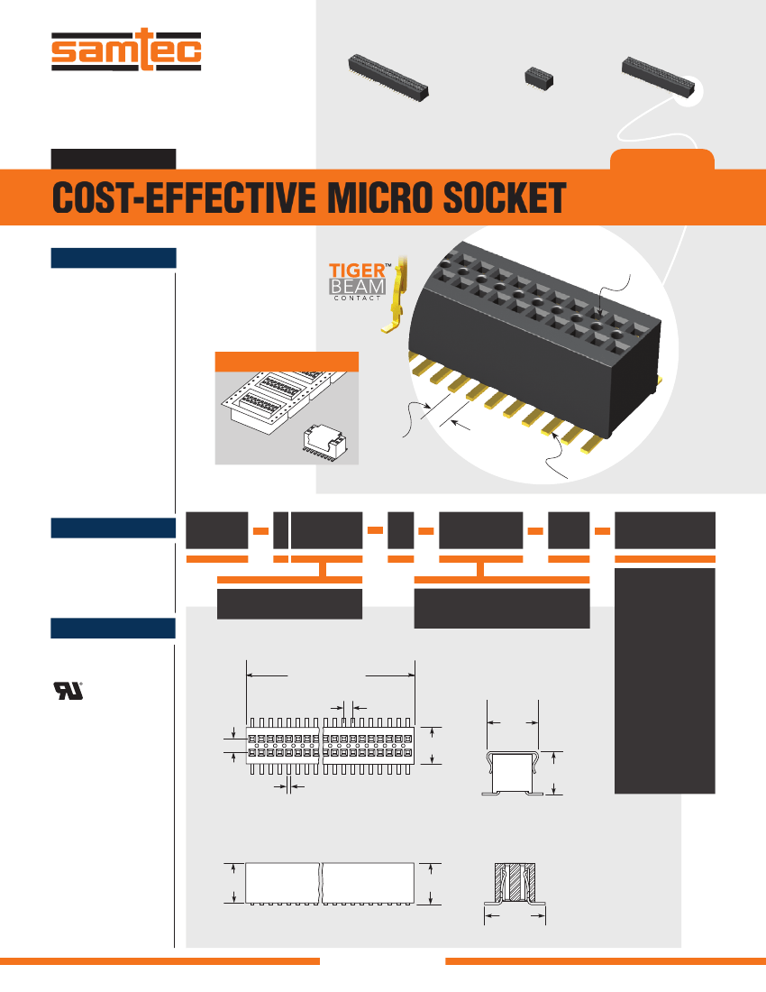
.8MM MICRO SOCKET STRIPS
| Parameter Name | Attribute value |
| Is it Rohs certified? | conform to |
| Maker | SAMTEC |
| Reach Compliance Code | compliant |
| ECCN code | EAR99 |
| Factory Lead Time | 2 weeks |
| Other features | M.PICK&PLACE PAD,TAPE&REEL PKG |
| body width | 0.125 inch |
| subject depth | 0.123 inch |
| body length | 0.284 inch |
| Body/casing type | PLUG |
| Connector type | BOARD CONNECTOR |
| Contact to complete cooperation | AU ON NI |
| Contact completed and terminated | Gold (Au) - with Nickel (Ni) barrier |
| Contact point gender | FEMALE |
| Contact material | BERYLLIUM COPPER |
| contact mode | RECTANGULAR |
| Contact resistance | 15 mΩ |
| Contact style | SQ PIN-SKT |
| Dielectric withstand voltage | 375VAC V |
| Durability | 100 Cycles |
| maximum insertion force | .556 N |
| Insulation resistance | 5000000000 Ω |
| Insulator color | BLACK |
| insulator material | LIQUID CRYSTAL POLYMER (LCP) |
| JESD-609 code | e4 |
| Manufacturer's serial number | CLE |
| Plug contact pitch | 0.031 inch |
| Match contact row spacing | 0.047 inch |
| Installation method | STRAIGHT |
| Installation type | BOARD |
| Number of connectors | ONE |
| PCB row number | 2 |
| Number of rows loaded | 2 |
| Maximum operating temperature | 125 °C |
| Minimum operating temperature | -65 °C |
| PCB contact pattern | RECTANGULAR |
| PCB contact row spacing | 3.9624 mm |
| Plating thickness | 10u inch |
| polarization key | POLARIZED HOUSING |
| Rated current (signal) | 0.75 A |
| Guideline | UL |
| reliability | COMMERCIAL |
| Terminal length | |
| Terminal pitch | 0.7874 mm |
| Termination type | SURFACE MOUNT |
| Total number of contacts | 18 |
| Evacuation force-minimum value | .3336 N |
| Base Number Matches | 1 |
 京公网安备 11010802033920号


