
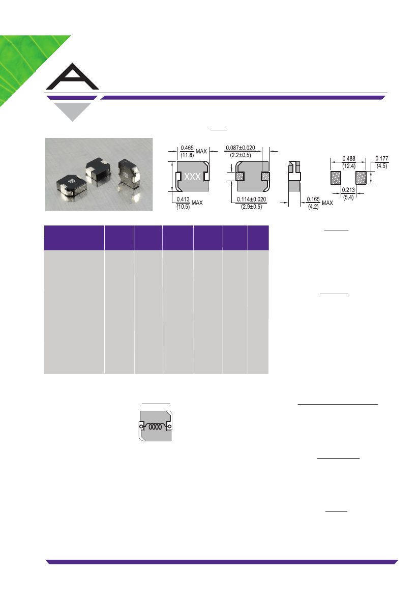
1 ELEMENT, 0.36 uH, GENERAL PURPOSE INDUCTOR, SMD
| Parameter Name | Attribute value |
| Is it Rohs certified? | conform to |
| Maker | ALLIED [Allied Electronics] |
| package instruction | 4741 |
| Reach Compliance Code | compli |
| ECCN code | EAR99 |
| uppercase and lowercase codes | 4741 |
| DC Resistance | 1.4 Ω |
| Nominal inductance(L) | 0.36 µH |
| Inductor Applications | HIGH CURRENT INDUCTOR |
| Inductor type | GENERAL PURPOSE INDUCTOR |
| JESD-609 code | e1 |
| Number of functions | 1 |
| Number of terminals | 2 |
| Maximum operating temperature | 125 °C |
| Minimum operating temperature | -55 °C |
| Shape/Size Description | RECTANGULAR PACKAGE |
| shield | NO |
| surface mount | YES |
| Terminal surface | Tin/Silver/Copper (Sn/Ag/Cu) |
| Terminal location | DUAL ENDED |
| Terminal shape | WRAPAROUND |
| Test frequency | 0.1 MHz |
| Tolerance | 20% |
| PCHC104H-R36M-RC | PCHC104H-100M-RC | PCHC104H-2R2M-RC | PCHC104H-4R7M-RC | PCHC104H-R56M-RC | PCHC104H-6R8M-RC | PCHC104H-R68M-RC | PCHC104H-3R3M-RC | PCHC104H-1R5M-RC | PCHC104H-R47M-RC | |
|---|---|---|---|---|---|---|---|---|---|---|
| Description | 1 ELEMENT, 0.36 uH, GENERAL PURPOSE INDUCTOR, SMD | 1 ELEMENT, 10 uH, GENERAL PURPOSE INDUCTOR, SMD | 1 ELEMENT, 2.2 uH, GENERAL PURPOSE INDUCTOR, SMD | 1 ELEMENT, 4.7 uH, GENERAL PURPOSE INDUCTOR, SMD | 1 ELEMENT, 0.56 uH, GENERAL PURPOSE INDUCTOR, SMD | 1 ELEMENT, 10 uH, GENERAL PURPOSE INDUCTOR, SMD | 1 ELEMENT, 0.68 uH, GENERAL PURPOSE INDUCTOR, SMD | 1 ELEMENT, 10 uH, GENERAL PURPOSE INDUCTOR, SMD | 1 ELEMENT, 1.5 uH, GENERAL PURPOSE INDUCTOR, SMD | 1 ELEMENT, 0.47 uH, GENERAL PURPOSE INDUCTOR, SMD |
| Is it Rohs certified? | conform to | conform to | conform to | conform to | conform to | conform to | conform to | - | conform to | conform to |
| Maker | ALLIED [Allied Electronics] | ALLIED [Allied Electronics] | ALLIED [Allied Electronics] | ALLIED [Allied Electronics] | ALLIED [Allied Electronics] | ALLIED [Allied Electronics] | ALLIED [Allied Electronics] | - | ALLIED [Allied Electronics] | ALLIED [Allied Electronics] |
| package instruction | 4741 | 4741 | 4741 | 4741 | 4741 | 4741 | 4741 | - | 4741 | 4741 |
| Reach Compliance Code | compli | compli | compli | compli | compli | compli | compli | - | compli | compli |
| ECCN code | EAR99 | EAR99 | EAR99 | EAR99 | EAR99 | EAR99 | EAR99 | - | EAR99 | EAR99 |
| uppercase and lowercase codes | 4741 | 4741 | 4741 | 4741 | 4741 | 4741 | 4741 | - | 4741 | 4741 |
| DC Resistance | 1.4 Ω | 35 Ω | 8.56 Ω | 13.5 Ω | 1.9 Ω | 24 Ω | 2.4 Ω | - | 7.5 Ω | 1.6 Ω |
| Nominal inductance(L) | 0.36 µH | 10 µH | 2.2 µH | 4.7 µH | 0.56 µH | 6.8 µH | 0.68 µH | - | 1.5 µH | 0.47 µH |
| Inductor Applications | HIGH CURRENT INDUCTOR | HIGH CURRENT INDUCTOR | HIGH CURRENT INDUCTOR | HIGH CURRENT INDUCTOR | HIGH CURRENT INDUCTOR | HIGH CURRENT INDUCTOR | HIGH CURRENT INDUCTOR | - | HIGH CURRENT INDUCTOR | HIGH CURRENT INDUCTOR |
| Inductor type | GENERAL PURPOSE INDUCTOR | GENERAL PURPOSE INDUCTOR | GENERAL PURPOSE INDUCTOR | GENERAL PURPOSE INDUCTOR | GENERAL PURPOSE INDUCTOR | GENERAL PURPOSE INDUCTOR | GENERAL PURPOSE INDUCTOR | - | GENERAL PURPOSE INDUCTOR | GENERAL PURPOSE INDUCTOR |
| JESD-609 code | e1 | e1 | e1 | e1 | e1 | e1 | e1 | - | e1 | e1 |
| Number of functions | 1 | 1 | 1 | 1 | 1 | 1 | 1 | - | 1 | 1 |
| Number of terminals | 2 | 2 | 2 | 2 | 2 | 2 | 2 | - | 2 | 2 |
| Maximum operating temperature | 125 °C | 125 °C | 125 °C | 125 °C | 125 °C | 125 °C | 125 °C | - | 125 °C | 125 °C |
| Minimum operating temperature | -55 °C | -55 °C | -55 °C | -55 °C | -55 °C | -55 °C | -55 °C | - | -55 °C | -55 °C |
| Shape/Size Description | RECTANGULAR PACKAGE | RECTANGULAR PACKAGE | RECTANGULAR PACKAGE | RECTANGULAR PACKAGE | RECTANGULAR PACKAGE | RECTANGULAR PACKAGE | RECTANGULAR PACKAGE | - | RECTANGULAR PACKAGE | RECTANGULAR PACKAGE |
| shield | NO | NO | NO | NO | NO | NO | NO | - | NO | NO |
| surface mount | YES | YES | YES | YES | YES | YES | YES | - | YES | YES |
| Terminal surface | Tin/Silver/Copper (Sn/Ag/Cu) | Tin/Silver/Copper (Sn/Ag/Cu) | Tin/Silver/Copper (Sn/Ag/Cu) | Tin/Silver/Copper (Sn/Ag/Cu) | Tin/Silver/Copper (Sn/Ag/Cu) | Tin/Silver/Copper (Sn/Ag/Cu) | Tin/Silver/Copper (Sn/Ag/Cu) | - | Tin/Silver/Copper (Sn/Ag/Cu) | Tin/Silver/Copper (Sn/Ag/Cu) |
| Terminal location | DUAL ENDED | DUAL ENDED | DUAL ENDED | DUAL ENDED | DUAL ENDED | DUAL ENDED | DUAL ENDED | - | DUAL ENDED | DUAL ENDED |
| Terminal shape | WRAPAROUND | WRAPAROUND | WRAPAROUND | WRAPAROUND | WRAPAROUND | WRAPAROUND | WRAPAROUND | - | WRAPAROUND | WRAPAROUND |
| Test frequency | 0.1 MHz | 0.1 MHz | 0.1 MHz | 0.1 MHz | 0.1 MHz | 0.1 MHz | 0.1 MHz | - | 0.1 MHz | 0.1 MHz |
| Tolerance | 20% | 20% | 20% | 20% | 20% | 20% | 20% | - | 20% | 20% |
 京公网安备 11010802033920号


