
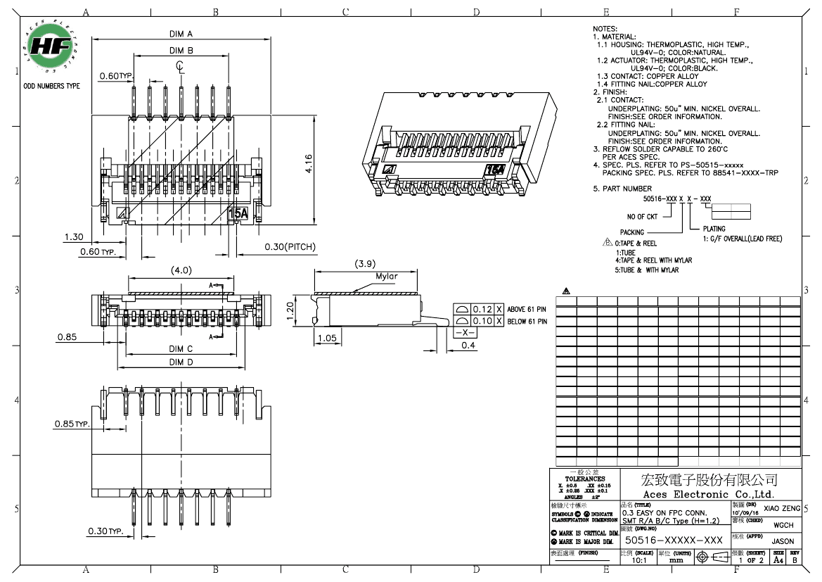
Card Edge Connector, 55 Contact(s), 1 Row(s), Right Angle, 0.012 inch Pitch, Surface Mount Terminal, Locking, Natural Insulator
| Parameter Name | Attribute value |
| Is it Rohs certified? | conform to |
| Maker | Aces Electronics Co., Ltd. |
| Reach Compliance Code | unknown |
| Board mount options | FITTING NAIL |
| body width | 0.047 inch |
| subject depth | 0.164 inch |
| body length | 0.74 inch |
| Connector type | FFC/FPC CONNECTOR |
| Contact to complete cooperation | AU ON NI |
| Contact completed and terminated | Gold (Au) - with Nickel (Ni) barrier |
| Contact material | COPPER ALLOY |
| contact mode | RECTANGULAR |
| Contact resistance | 80 mΩ |
| Dielectric withstand voltage | 250VAC V |
| Durability | 10 Cycles |
| Insulation resistance | 50000000 Ω |
| Insulator color | NATURAL |
| insulator material | THERMOPLASTIC |
| JESD-609 code | e4 |
| Plug contact pitch | 0.012 inch |
| Installation option 1 | LOCKING |
| Installation option 2 | SLIDE |
| Installation method | RIGHT ANGLE |
| Installation type | BOARD |
| PCB row number | 2 |
| Number of rows loaded | 1 |
| Maximum operating temperature | 85 °C |
| Minimum operating temperature | -40 °C |
| PCB contact pattern | STAGGERED |
| Plating thickness | FLASH inch |
| Guideline | UL |
| reliability | COMMERCIAL |
| Terminal pitch | 0.6096 mm |
| Termination type | SURFACE MOUNT |
| Total number of contacts | 55 |
| Base Number Matches | 1 |
 京公网安备 11010802033920号


