

HCMOS/LSTTL Output Clock Oscillator, 9.6MHz Min, 32MHz Max, ROHS COMPLIANT PACKAGE-4
| Parameter Name | Attribute value |
| Is it lead-free? | Lead free |
| Is it Rohs certified? | conform to |
| Maker | Cardinal Components |
| Reach Compliance Code | compliant |
| Other features | BULK |
| Maximum control voltage | 4.5 V |
| Minimum control voltage | 0.5 V |
| maximum descent time | 10 ns |
| Frequency Adjustment - Mechanical | YES |
| Frequency offset/pull rate | 20 ppm |
| frequency stability | 15% |
| linearity | 15% |
| Manufacturer's serial number | CC127 |
| Installation features | SURFACE MOUNT |
| Maximum operating frequency | 32 MHz |
| Minimum operating frequency | 9.6 MHz |
| Maximum operating temperature | 85 °C |
| Minimum operating temperature | -40 °C |
| Oscillator type | HCMOS/LSTTL |
| Output load | 10 LS TTL, 15 pF |
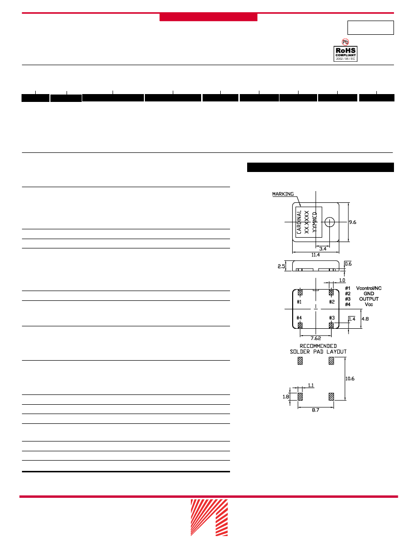
| physical size | 11.4mm x 9.6mm x 2.5mm |
| longest rise time | 10 ns |
| Maximum supply voltage | 5.25 V |
| Minimum supply voltage | 4.75 V |
| Nominal supply voltage | 5 V |
| surface mount | YES |
| maximum symmetry | 40/60 % |
 京公网安备 11010802033920号


