DB1501S ~ DB1507S
Elektronische Bauelemente
VOLTAGE 50 V ~ 1000 V
1.5 Amp Surface Mount Bridge Rectifiers
RoHS Compliant Product
A suffix of “-C” specifies halogen & lead-free
FEATURES
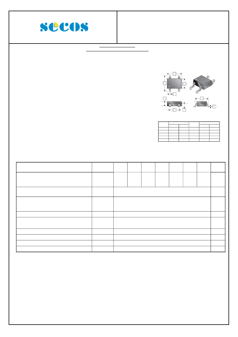
DB-1S
-
A
+
Low forward voltage drop, high current capability
Rating to 1000V PRV
Ideal for printed circuit board
Reliable low cost construction utilizing molded plastic technique
results in inexpensive products
Lead tin Pb / Sn copper
The plastic material has UL flammability classification 94V-0
B
J
E
D
~
~
C
L
MECHANICAL DATA
F
M
Polarity: As marked on Body
Weight:0.02 ounces, 0.38 grams
Mounting position: Any
REF.
A
B
C
D
E
MAXIMUM RATINGS AND ELECTRICAL CHARACTERISTICS
Rating at 25℃ ambient temperature unless otherwise specified.
Single phase, half wave, 60Hz, resistive or inductive load.
For capacitive load, de-rate current by 20%.
PARAMETERS
Peak Repetitive Peak Reverse Voltage
Working Peak Reverse Voltage
DC Blocking Voltage
Maximum Average Forward Rectified Current
@T
A
=40℃
Peak Forward Surge Current 8.3 ms Single Half
Sine-Wave Super Imposed on Rated Load
(JEDEC Method)
Maximum Forward Voltage at 1.5 A DC
Maximum DC Reverse Current
at Rated DC Blocking Voltage
I t Rating for Fusing (t<8.3ms)
Typical Junction Capacitance Per Element (Note1)
Typical Thermal Resistance (Note2)
2
Millimeter
Min.
Max.
8.20
8.80
10.0
10.3
7.80
8.50
3.15
3.40
6.20
6.50
REF.
F
J
L
M
Millimeter
Min.
Max.
5.00
5.20
0.95
1.20
0.20
0.35
1.40
1.60
SYMBOL
DB
1501S
DB
1502S
DB
1503S
DB
1504S
DB
1505S
DB
1506S
DB
1507S
UNIT
V
A
A
V
uA
A
2
s
pF
℃/W
℃
V
RRM
V
RMS
V
DC
I
(AV)
I
FSM
V
F
I
R
I
2
t
C
J
R
θJA
T
J
, T
STG
50
35
50
100
70
100
200
140
200
400
280
400
1.5
50
1.1
10
500
10.4
25
40
-55 ~ 150
600
420
600
800
560
800
1000
700
1000
@T
J
=25℃
@T
J
=125℃
Operating and Storage temperature range
Note: 1. Measured at 1.0 MHz and applied reverse voltage of 4.0 V DC
2. Thermal resistance from junction to ambient mounted on P.C.B. with 0.5*0.5"(13*13mm) copper pads.
01-Sep-2010 Rev. C
Page 1 of 2
DB1501S ~ DB1507S
Elektronische Bauelemente
VOLTAGE 50 V ~ 1000 V
1.5 Amp Surface Mount Bridge Rectifiers
RATINGS AND CHARACTERISTIC CURVES
FIG. 1 - Forward Current Derating Curve
1.50
PEAK FORWARD SURGE CURRENT,
AMPERES
AVERAGE FORWARD CURRENT
AMPERES
FIG.2-MAXIMUM NON-REPETITIVE
SURGE CURRENT
50
40
30
20
10
0
1
2
5
10
20
50
100
NUMBER OF CYCLES AT 60Hz
FIG.4-TYPICAL FORWARD CHARACTERISTICS
10
INSTANTANEOUS FORWARD CURRENT,(A)
SINGE HALF-SINE-WAVE
(JEDEC METHOD)
1.25
1.00
0.75
0.50
0.25
0.00
50
SINGLE PHASE HALF WAVE 60Hz
RESISTIVE OR INDUCTIVE LOAD
100
150
AMBIENT TEMPERATURE,
o
C
FIG.3-TYPICAL JUNCTION CAPACITANCE
100
CAPACITANCE(pF)
1.0
10
0.1
T
J
=25
o
C
,f=1MH
Z
T
J
=25
o
C
PULSE WIDTH:300us
2% DUTY CYCLE
1.0
0.1
1.0
4.0
10.0
100
0.01
0
0.2
0.4
0.6
0.8
1.0
1.2
1.4
1.6
1.8
REVERSE VOLTAGE,(VOLTS)
INSTANTANEOUS FORWARD VOLTAGE,VOLTS
FIG.5-TYPICAL REVERSE CHARACTERISTICS
100
INSTANTANEOUS REVERSE CURRENT,(uA)
T
J
=125
o
C
10
1.0
o
T
J
=25
C
0.1
0.01
0
20
40
60
80
100
120
140
PERCENT OF RATED PEAK REVERSE VOLTAGE,(%)
01-Sep-2010 Rev. C
Page 2 of 2
This datasheet has been downloaded from:
www.EEworld.com.cn
Free Download
Daily Updated Database
100% Free Datasheet Search Site
100% Free IC Replacement Search Site
Convenient Electronic Dictionary
Fast Search System
www.EEworld.com.cn
All Datasheets Cannot Be Modified Without Permission
Copyright © Each Manufacturing Company

 京公网安备 11010802033920号


