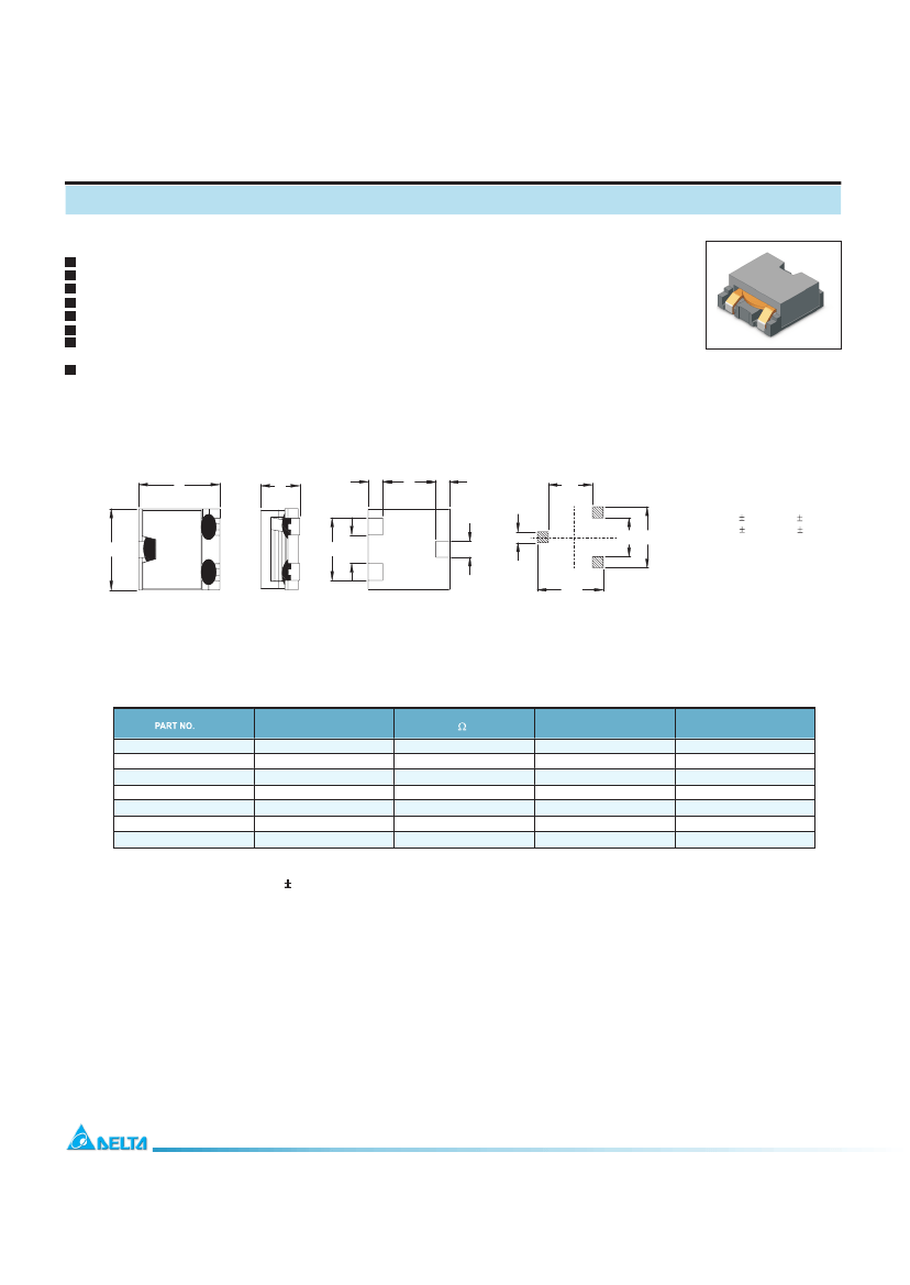
General Purpose Inductor, 0.6uH, 20%, 1 Element, SMD, 5050-22, CHIP, 5050-22, ROHS COMPLIANT
| Parameter Name | Attribute value |
| Maker | Delta Electronics |
| package instruction | CHIP, 5050-22, ROHS COMPLIANT |
| Reach Compliance Code | compliant |
| ECCN code | EAR99 |
| uppercase and lowercase codes | 5050-22 |
| DC Resistance | 0.0015 Ω |
| Nominal inductance(L) | 0.6 µH |
| Inductor Applications | POWER INDUCTOR |
| Inductor type | GENERAL PURPOSE INDUCTOR |
| Manufacturer's serial number | HMU1356L |
| Number of functions | 1 |
| Number of terminals | 3 |
| Shape/Size Description | RECTANGULAR PACKAGE |
| shield | YES |
| surface mount | YES |
| Terminal shape | WRAPAROUND |
| Test frequency | 0.1 MHz |
| Tolerance | 20% |
| HMU1356L-0R6 | HMU1356L-1R5 | HMU1356L-4R0 | HMU1356L-8R2 | HMU1356L-6R0 | HMU1356L-2R5 | HMU1356L-100 | |
|---|---|---|---|---|---|---|---|
| Description | General Purpose Inductor, 0.6uH, 20%, 1 Element, SMD, 5050-22, CHIP, 5050-22, ROHS COMPLIANT | General Purpose Inductor, 1.5uH, 20%, 1 Element, SMD, 5050-22, CHIP, 5050-22, ROHS COMPLIANT | General Purpose Inductor, 4uH, 20%, 1 Element, SMD, 5050-22, CHIP, 5050-22, ROHS COMPLIANT | General Purpose Inductor, 8.2uH, 20%, 1 Element, SMD, 5050-22, CHIP, 5050-22, ROHS COMPLIANT | General Purpose Inductor, 6uH, 20%, 1 Element, SMD, 5050-22, CHIP, 5050-22, ROHS COMPLIANT | General Purpose Inductor, 2.5uH, 20%, 1 Element, SMD, 5050-22, CHIP, 5050-22, ROHS COMPLIANT | General Purpose Inductor, 10uH, 20%, 1 Element, SMD, 5050-22, CHIP, 5050-22, ROHS COMPLIANT |
| Maker | Delta Electronics | Delta Electronics | Delta Electronics | Delta Electronics | Delta Electronics | Delta Electronics | Delta Electronics |
| package instruction | CHIP, 5050-22, ROHS COMPLIANT | 5050-22 | CHIP, 5050-22, ROHS COMPLIANT | CHIP, 5050-22, ROHS COMPLIANT | CHIP, 5050-22, ROHS COMPLIANT | CHIP, 5050-22, ROHS COMPLIANT | CHIP, 5050-22, ROHS COMPLIANT |
| Reach Compliance Code | compliant | unknown | compliant | compliant | compliant | compliant | compliant |
| ECCN code | EAR99 | EAR99 | EAR99 | EAR99 | EAR99 | EAR99 | EAR99 |
| uppercase and lowercase codes | 5050-22 | 5050-22 | 5050-22 | 5050-22 | 5050-22 | 5050-22 | 5050-22 |
| DC Resistance | 0.0015 Ω | 0.0022 Ω | 0.0054 Ω | 0.0114 Ω | 0.008 Ω | 0.0034 Ω | 0.0135 Ω |
| Nominal inductance(L) | 0.6 µH | 1.5 µH | 4 µH | 8.2 µH | 6 µH | 2.5 µH | 10 µH |
| Inductor Applications | POWER INDUCTOR | POWER INDUCTOR | POWER INDUCTOR | POWER INDUCTOR | POWER INDUCTOR | POWER INDUCTOR | POWER INDUCTOR |
| Inductor type | GENERAL PURPOSE INDUCTOR | GENERAL PURPOSE INDUCTOR | GENERAL PURPOSE INDUCTOR | GENERAL PURPOSE INDUCTOR | GENERAL PURPOSE INDUCTOR | GENERAL PURPOSE INDUCTOR | GENERAL PURPOSE INDUCTOR |
| Manufacturer's serial number | HMU1356L | HMU1356L | HMU1356L | HMU1356L | HMU1356L | HMU1356L | HMU1356L |
| Number of functions | 1 | 1 | 1 | 1 | 1 | 1 | 1 |
| Number of terminals | 3 | 3 | 3 | 3 | 3 | 3 | 3 |
| Shape/Size Description | RECTANGULAR PACKAGE | RECTANGULAR PACKAGE | RECTANGULAR PACKAGE | RECTANGULAR PACKAGE | RECTANGULAR PACKAGE | RECTANGULAR PACKAGE | RECTANGULAR PACKAGE |
| shield | YES | YES | YES | YES | YES | YES | YES |
| surface mount | YES | YES | YES | YES | YES | YES | YES |
| Terminal shape | WRAPAROUND | WRAPAROUND | WRAPAROUND | WRAPAROUND | WRAPAROUND | WRAPAROUND | WRAPAROUND |
| Test frequency | 0.1 MHz | 0.1 MHz | 0.1 MHz | 0.1 MHz | 0.1 MHz | 0.1 MHz | 0.1 MHz |
| Tolerance | 20% | 20% | 20% | 20% | 20% | 20% | 20% |
 京公网安备 11010802033920号


