

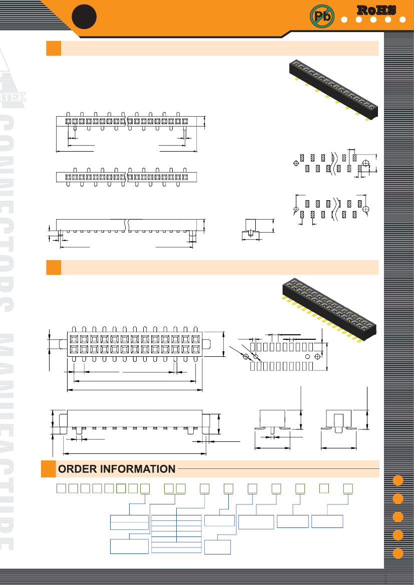
Board Connector, 34 Contact(s), 1 Row(s), Female, Straight, 0.05 inch Pitch, Surface Mount Terminal, Black Insulator, Receptacle
| Parameter Name | Attribute value |
| Is it lead-free? | Lead free |
| Is it Rohs certified? | conform to |
| Objectid | 1164499445 |
| Reach Compliance Code | unknown |
| ECCN code | EAR99 |
| Other features | ROHS COMPLIANT |
| Board mount options | PEG |
| body width | 0.071 inch |
| subject depth | 0.094 inch |
| body length | 1.823 inch |
| Body/casing type | RECEPTACLE |
| Connector type | BOARD CONNECTOR |
| Contact to complete cooperation | TIN |
| Contact completed and terminated | Tin (Sn) |
| Contact point gender | FEMALE |
| Contact material | COPPER ALLOY |
| contact mode | RECTANGULAR |
| Contact resistance | 20 mΩ |
| Contact style | SQ PIN-SKT |
| Dielectric withstand voltage | 500VAC V |
| Insulation resistance | 1000000000 Ω |
| Insulator color | BLACK |
| insulator material | NYLON |
| JESD-609 code | e3 |
| Manufacturer's serial number | PS3M21 |
| Plug contact pitch | 0.05 inch |
| Installation method | STRAIGHT |
| Installation type | BOARD |
| Number of connectors | ONE |
| PCB row number | 2 |
| Number of rows loaded | 1 |
| Maximum operating temperature | 105 °C |
| Minimum operating temperature | -40 °C |
| PCB contact pattern | STAGGERED |
| PCB contact row spacing | 2.5908 mm |
| Rated current (signal) | 1 A |
| Guideline | UL |
| reliability | COMMERCIAL |
| Terminal pitch | 2.54 mm |
| Termination type | SURFACE MOUNT |
| Total number of contacts | 34 |
 京公网安备 11010802033920号


