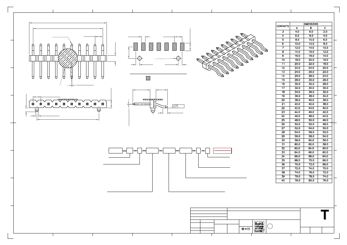
EEWORLDEEWORLDEEWORLD

Part Number

Search

BF036-19-C-0250-0250-0250-N-D

Description
Board Connector, 19 Contact(s), 1 Row(s), Male, Right Angle, 0.079 inch Pitch, Surface Mount Terminal, Black Insulator,
CategoryThe connector    The connector   
File Size177KB,1 Pages
ManufacturerGlobal Connector Technology
Environmental Compliance
Download Datasheet Parametric View All

BF036-19-C-0250-0250-0250-N-D Overview

Board Connector, 19 Contact(s), 1 Row(s), Male, Right Angle, 0.079 inch Pitch, Surface Mount Terminal, Black Insulator,

BF036-19-C-0250-0250-0250-N-D Parametric

Parameter NameAttribute value
Is it Rohs certified?conform to
Objectid314622983
Reach Compliance Codecompliant
ECCN codeEAR99
body width0.079 inch
subject depth0.157 inch
body length1.496 inch
Connector typeBOARD CONNECTOR
Contact to complete cooperationSN ON NI
Contact completed and terminatedTin (Sn) - with Nickel (Ni) barrier
Contact point genderMALE
Contact materialCOPPER ALLOY
contact modeRECTANGULAR
Contact resistance20 mΩ
Contact styleSQ PIN-SKT
Dielectric withstand voltage500VAC V
Durability100 Cycles
Insulation resistance1000000000 Ω
Insulator colorBLACK
insulator materialNYLON
JESD-609 codee3
Manufacturer's serial numberBF036
Plug contact pitch0.079 inch
Installation methodRIGHT ANGLE
Installation typeBOARD
Number of connectorsONE
PCB row number1
Number of rows loaded1
Maximum operating temperature105 °C
Minimum operating temperature-40 °C
PCB contact patternRECTANGULAR
Rated current (signal)2 A
GuidelineUL
reliabilityCOMMERCIAL
Terminal pitch2.0066 mm
Termination typeSURFACE MOUNT
Total number of contacts19
B±0.35
H
A±0.25
Pin 0.50 sq
2.00
1.50
1.00
2.00
G
3.00
2x Ø1.00
1.00
1.00
Recommended PCB Layout
Ø 5 .0
0
F
Solder Area
2° Max. Sway
1.00
2.00 Typ.
2.00
Either direction
at the top
D±0.2
E±0.2
2° Max. Toe
Either direction
at the top
E
0.15
2x ø0.80
F±0.2
C±0.20
D
Ordering Grid
Specifications
规格
BF036
XX
X
F+1.0
XXXX
XXXX
XXXX
X
X
C
B
A
Current Rating
电流额定值
: 2.0 Amp
No. of Contacts
Insulation Resistance
绝缘电阻值
: 1000 MΩ min.
03 to 40
Contact Resistance
接触电阻值
: 20 mΩ max.
Contact Plating
Dielectric Withstanding
耐电压
: 500V AC
A = Gold Flash All Over
(Standard)
Operating Temperature
工½温度
:
B = Selective Gold Flash Contact Area/
Gold Plating: -40°C to +125°C
Tin On Tail
Tin Plating: -40°C to +105°C
C = Tin All Over
Contact Material
端子物料
: Copper Alloy
G = 10µ" Gold Contact Area/Tin On Tail
Insulator Material
绝缘½物料
:
I = 30µ" Gold Contact Area/Tin On Tail
Standard
标准物料
: Polyamide, Nylon 6T, UL 94V-0
Options
可选物料
: Polyester, LCP, UL 94V-0
Dimension D
(1/100mm) (Post Length)
Soldering Process
可焊性
:
0400 = 4.00mm
(Standard)
Nylon 6T (Standard
标准物料
) -
Or specify custom Post Length
IR Reflow
回流焊
: 260°C for 10 sec.
eg 0250 = 2.50mm
Wave
波峰焊
:230°C for 5-10 sec.
Manual Solder
人工焊接
: 350°C for 3-5 sec
LCP (Option
可选物料
) -
IR Reflow
回流焊
: 260°C for 10 sec.
Wave
波峰焊
:250°C for 5-10 sec.
Manual Solder
人工焊接
: 350°C for 3-5 sec
Mates with
配套之母座
(Subject to pin length
在端子长度适合的条件下
):
BF070
BF085
BF090
Request Samples
and Quotation
Packing Options
C = Tape and Reel with Film
(Standard)
D = Tube
Insulator Material
N = Nylon 6T
(Standard)
L = LCP
Dimension F
(1/100mm) (Pin Curve to End of Pin)
0127 = 1.27mm
(Standard)
Or specify custom 'Pin Curve to End of Pin' length
eg 0250 = 2.50mm
Dimension E
(1/100mm) (Insulator to End of Pin)
0300 = 3.00mm
(Standard)
Or specify custom 'Insulator to End of Pin' length
eg 0250 = 2.50mm
Part Number
Product Description
BF036
Drawing Date
19th May 2010
By
Detail
Revision
Date
C2
10/03/15
AJO
Length
2.00mm Pitch Pin Header
Single Row, SMT, Horizontal with Locating Peg
Tolerances
(Except as Noted)
Angle
1
2
3
4
5
X.° ± 5°
X. ± 0.30
X.X° ± 3°
X.X ± 0.25
X.XX ± 0.15 X.XX° ± 2°
X.XXX ± 0.10 X.XXX° ± 1°
Units:
Metric (mm)
C
7
3rd Angle Projection
This drawing is confidential and
copyright of Global Connector
Technology, Ltd (GCT).
This drawing must not be copied
or disclosed without written
consent. E & OE
Global Connector Technology
GC
Drawn By
SA
www.gct.co
Not to
Scale
Sheet No.
1/1
6
8
How can this damped oscillation waveform be generated?
Hi everyone, the waveform in the above figure is a damped oscillation waveform generated by charging an inductor for 5us and discharging it. How can I realize this circuit? Thank you....
PSIR RF/Wirelessly
[EEWORLD module arrangement] + ultrasonic module
[i=s] This post was last edited by paulhyde on 2014-9-15 03:01 [/i] [local]1[/loc for your convenience...
kevinswen Electronics Design Contest
Ov7670 image acquisition source program based on TINYM0 LPC1114
[size=4]After a month of preparation and two weeks of program debugging, the application of TINYM0 development board (LPC1114 chip) was realized. The image was collected by OV7670 with FIFO image acqu...
灞波儿奔 Microcontroller MCU
Pingtouge Scenario-based Bluetooth Mesh Gateway Program Burning
To burn the Pingtou Ge scenario-based Bluetooth Mesh gateway program, you need to refer to thedocument and use thesoftware package andtool. If you only read the manual, there are still some places tha...
littleshrimp Domestic Chip Exchange
Introduction to allegro file encryption method
[p=26, null, left][color=rgb(0, 0, 0)][size=3]Sometimes you need to send a PCB drawing to someone else, but you don’t want them to operate on the file. There are two ways to do this: one is to prevent...
ohahaha PCB Design

EEWorld
subscription
account

EEWorld
service
account

Automotive
development
circle

Robot
development
community

Index Files: 1649  2451  1252  751  362  34  50  26  16  8 
Datasheet   0 1 2 3 4 5 6 7 8 9 A B C D E F G H I J K L M N O P Q R S T U V W X Y Z
Room 1530, 15th Floor, Building B, No. 18 Zhongguancun Street, Haidian District, Beijing Telephone: (010) 82350740 Postal Code: 100190
Copyright © 2005-2026 EEWORLD.com.cn, Inc. All rights reserved 京ICP证060456号 京ICP备10001474号-1 电信业务审批[2006]字第258号函 京公网安备 11010802033920号