ATC G E NE R A L P U R P O S E C A PA C I T ORS : X5 R DI ELE CT RI C
Electrical Characteristics
Capacitance Range:
0.1 µF to 33 µF
Temperature Coefficentof Capacitance:
± 15% with 0 Vdc applied
Operating Temperature Range:
-55°C to +85°C
Dissipation Factor:
5% (max.) @ + 25°C, @1 KHz @1.0 +/- 0.2 VRMS
See Page 9 for DF Exceptions for X5R
Insulation Resistance:
@ + 25°C and rated Vdc:10,000 megohms (min.) or
500 ohm-farads (min.), whichever is less
Aging:
3% (max.) per decade hr.
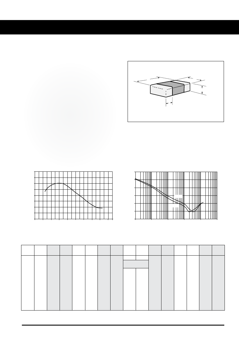
Dimension Drawing
L
W
T (MAX.)
MB
Dielectric Withstanding Voltage:
250% WVDC for WVDC < 200V
150% WVDC for 200V < WVDC
≤
500V
120% WVDC for WVDC > 500V
Applied for 5 ±1 sec.
Note:
Unless otherwise specified all test data is at + 25°C.
20
X5R Temperature Coefficient of Capacitance
X5R Impedance vs. Frequency
1000
100
% Capacitance Change
15
10
5
0
-5
-10
-15
-20
-80
-60
-40
-20
0
20
40
60
80
100
Impedance (Ohms)
10
1
0.1
10 µF
4.7 µF
0.01
0.001
1
10
100
1000
10000
100000
Temperature °C
Frequency (KHz)
Standard EIA Capacitance Values Reference Chart
Cap.
Code
0R5
1R0
1R2
1R5
1R8
2R2
2R7
3R3
3R9
4R7
5R6
6R8
Cap.
pF
0.5
1.0
1.2
1.5
1.8
2.2
2.7
3.3
3.9
4.7
5.6
6.8
Cap.
Code
8R2
100
120
150
180
220
270
330
390
470
560
680
Cap.
pF
8.2
10
12
15
18
22
27
33
39
47
56
68
Cap.
Code
820
101
121
151
181
221
271
331
391
471
561
681
Cap.
pF
82
100
120
150
180
220
270
330
390
470
560
680
Cap.
Code
821
102
122
152
182
222
272
332
392
472
562
682
Cap.
pF
820
1000
1200
1500
1800
2200
2700
3300
3900
4700
5600
6800
Cap.
Code
822
Cap.
Code
103
123
153
183
223
273
333
393
473
Cap.
pF
8200
Cap.
µF
.010
.012
.015
.018
.022
.027
.033
.039
.047
Cap.
Code
563
683
823
104
124
154
184
224
274
334
394
474
Cap.
µF
.056
.068
.082
.10
.12
.15
.18
.22
.27
.33
.39
.47
Cap.
Code
564
684
824
105
125
155
185
225
275
335
395
475
Cap.
µF
.56
.68
.82
1.0
1.2
1.5
1.8
2.2
2.7
3.3
3.9
4.7
Cap.
Code
565
685
825
106
126
156
186
226
276
336
Cap.
µF
5.6
6.8
8.2
10.0
12.0
15.0
18.0
22.0
27.0
33.0
A M E R I C A N
5
ATC North America
sales@atceramics.com
T E C H N I C A L
ATC Europe
saleseur@atceramics.com
C E R A M I C S
ATC Asia
sales@atceramics-asia.com
w ww.a t c er a m ic s .co m
ATC G E NE R A L P U R P O S E C A PA C I T ORS : X5 R DI ELE CT RI C
Selection Guide
Case Size
Length (L)
Width (W)
Tol. L & W
T Max.
Term. (MB) Min.
Max.
Min. Cap.
Max. Cap. (code)
& WVDC
10V
16V
25V
50V
Dimensions shown in inches (mm)
Higher voltages available upon request.
105
104
225
105
564
106
335
225
224
106
106
685
226
106
106
336
336
106
0402
.040 (1.02)
.020 (0.51)
±.004 (0.10)
.024 (0.61)
.004
.014
(.10)
(.36)
104
0603
.063 (1.60)
.031 (0.80)
±.005 (0.12)
.035 (0.89)
.004
.015
(.10)
(.38)
474
0805
.079 (2.00)
.049 (1.25)
±.008 (0.2)
.059 (1.50)
.010
.030
(.25)
(.76)
224
1206
.125 (3.18)
.063 (1.60)
±.008 (0.2)
.072 (1.83)
.010
.030
(.25)
(.76)
105
1210
.125 (3.18)
.100 (2.54)
±.008 (0.2)
.110 (2.79)
.010
.030
(.25)
(.76)
335
1812
.180 (4.57)
.125 (3.18)
±.012 (.305)
.118 (3.00)
.010
.030
(.25)
(.76)
106
Part Number Code
0805
Size Code
Temperature Characteristic
Capacitance Code: First 2 Significant Digits For Capacity.
Indicates number of zeros following digits of
capacitance in picofarads R=Decimal Point
CAPACITANCE TOLERANCE
K
M
Code
±20%
±10%
Tol.
WVDC
X5R
10
6
K
T
A
A
T
Packaging: T=7” Reel,
B=Tape Strip
Marking: A=No mark
S=EIA Code - (Special Order)
WVDC Code A 7 1 2
3
4
5
6
8
9
10 16 25 50 100* 200* 500* 1000* 2000* 5000*
*
Special Order - Consult Factory
Termination Code
T = Tin plated over Nickel Barrier (Standard),
RoHS Compliant
W = Tin/Lead, Solder Plated over Nickel Barrier**
**
Consult ATC for availability
A M E R I C A N
ATC North America
sales@atceramics.com
T E C H N I C A L
ATC Europe
saleseur@atceramics.com
C E R A M I C S
ATC Asia
sales@atceramics-asia.com
w ww.a t c er a m ic s .co m
6

 京公网安备 11010802033920号


