I. Project Introduction:
This is a USB 3.0 hub based on the VL812, featuring one USB 3.0 input, four USB 3.0 outputs, and a single 5V power supply. It integrates internal 5V to 3.3V and 5V to 1.2V converters. It comes with firmware and is ready to use after soldering. It uses a TYPE-B input interface, making soldering and wiring convenient. The measured maximum speed is 461MB/s.
II. Chip Introduction: The VL812
ultra-high-speed USB hub controller
supports four modes: ultra-high speed, high speed, full speed, and low speed. It
has four downstream ports and one upstream port. An
integrated voltage regulator generates all necessary chip power from the 5V input. It
supports dual status indicator lights
and comprehensive USB battery charging support.

Figure 1 - Block Diagram
. III. Circuit Analysis:
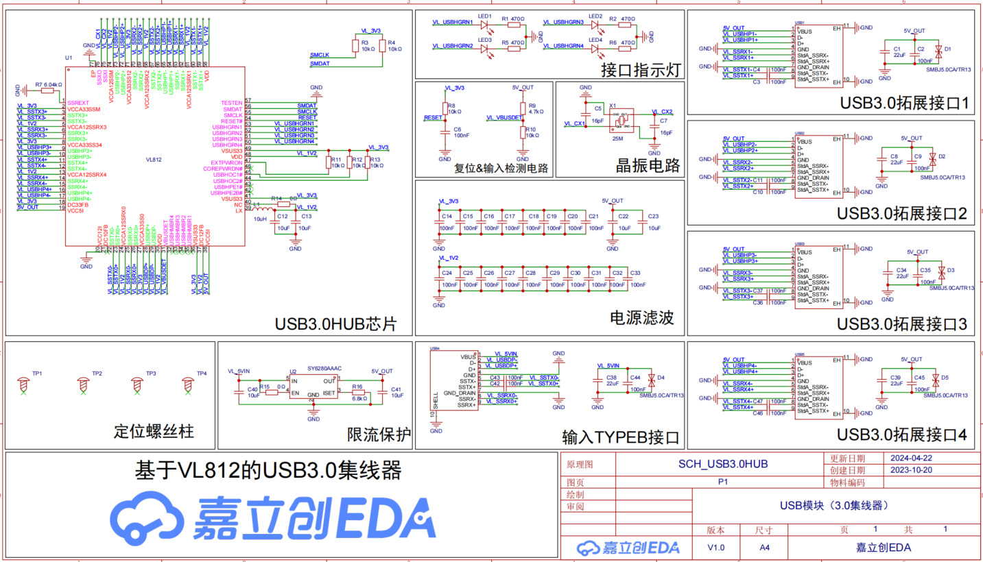
Figure 2 - Schematic Diagram
. 1. Main Control Chip Circuit
: The VL812 chip symbol is edited to distinguish three parts: power pins, hub function pins, and special function pins. Some pull-up/pull-down resistors and LC filtering on the LX pin are not mentioned in the chip datasheet and require reference to official chip design examples.
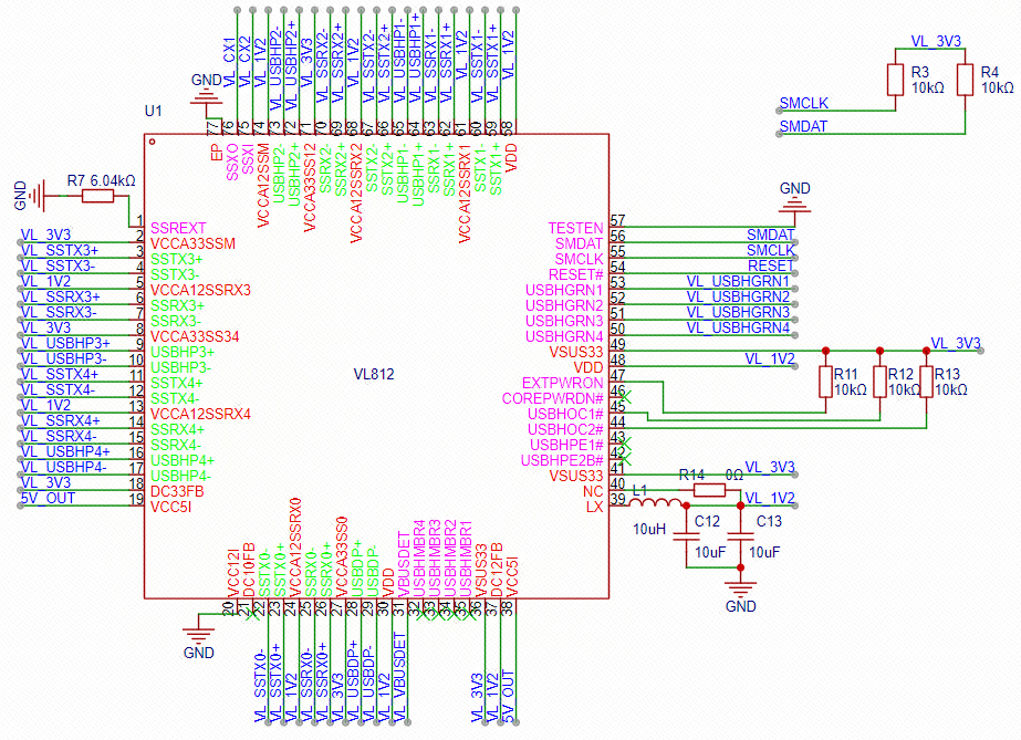
Figure 3 - Main Control Chip Circuit
2. Interface Indicator Circuit
According to the datasheet, when a device is inserted, the corresponding insertion pin outputs a high level. An indicator light and current-limiting resistor are added accordingly as an insertion indication. To enhance the display effect, the indicator light uses RGB3 three-color gradient and has built-in RC, requiring no external control.

Figure 4 - Interface Indicator Circuit
3. Reset & Input Detection Circuit
The VL812 uses a low-level reset. Here, a 10K resistor and a 100nF capacitor are used for power-on reset to meet timing requirements. A voltage divider circuit composed of 4.7K and 10K resistors is used to divide the 5V voltage to approximately 3.4V. Note that 5V cannot be directly input to the pin, as this may damage the chip.
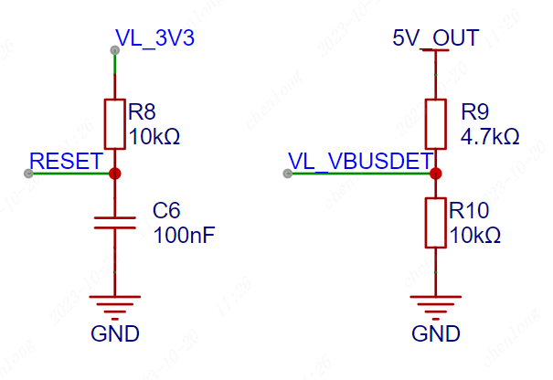
Figure 5 - Reset & Input Detection Circuit
4. Crystal Oscillator Circuit A
25MHz passive crystal oscillator is used to provide a stable clock signal to the main control chip. The matching capacitor needs to be selected based on the load capacitor of the purchased crystal oscillator. Alternatively, an active crystal oscillator can be considered to further improve stability.
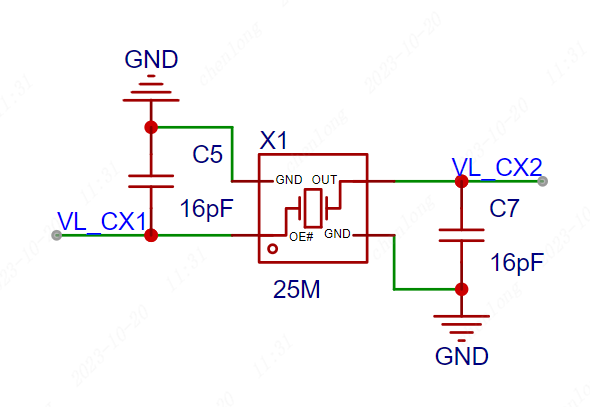
Figure 6 - Crystal Oscillator Circuit
5. Current Limiting Protection Circuit
Considering that some users use laptops, the output current of a laptop 3.0 interface is generally around 1A. Here, the SY6280 current limiting protection chip is used to limit the input current to 1A to prevent the laptop interface from burning out. However, if all four USB output ports are connected to USB 3.0, insufficient power supply may occur. In this case, it is necessary to consider the actual computer situation and set the current limiting resistor R16 to obtain a larger current. The EN pin can be directly input; a high level is normal operation. The 0-ohm resistor here is a test resistor.
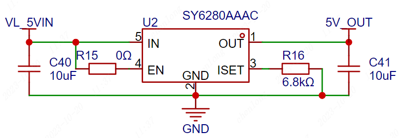
Figure 7 Current Limiting Protection Circuit
6. Input Interface Circuit The
USB 3.0 protocol is different from the 2.0 protocol. The USB 3.0 interface has an additional set of differential data input signals. The commonly used TYPE-C and TYPE-B interfaces have made certain modifications to the interface to match these two protocols. Among them, the TYPE-C interface only has differential data lines on the 24-pin connector, which cannot be simply distinguished by color. Please pay attention when purchasing!

Figure 8 shows the USB 2.0-TYPE-C interface.
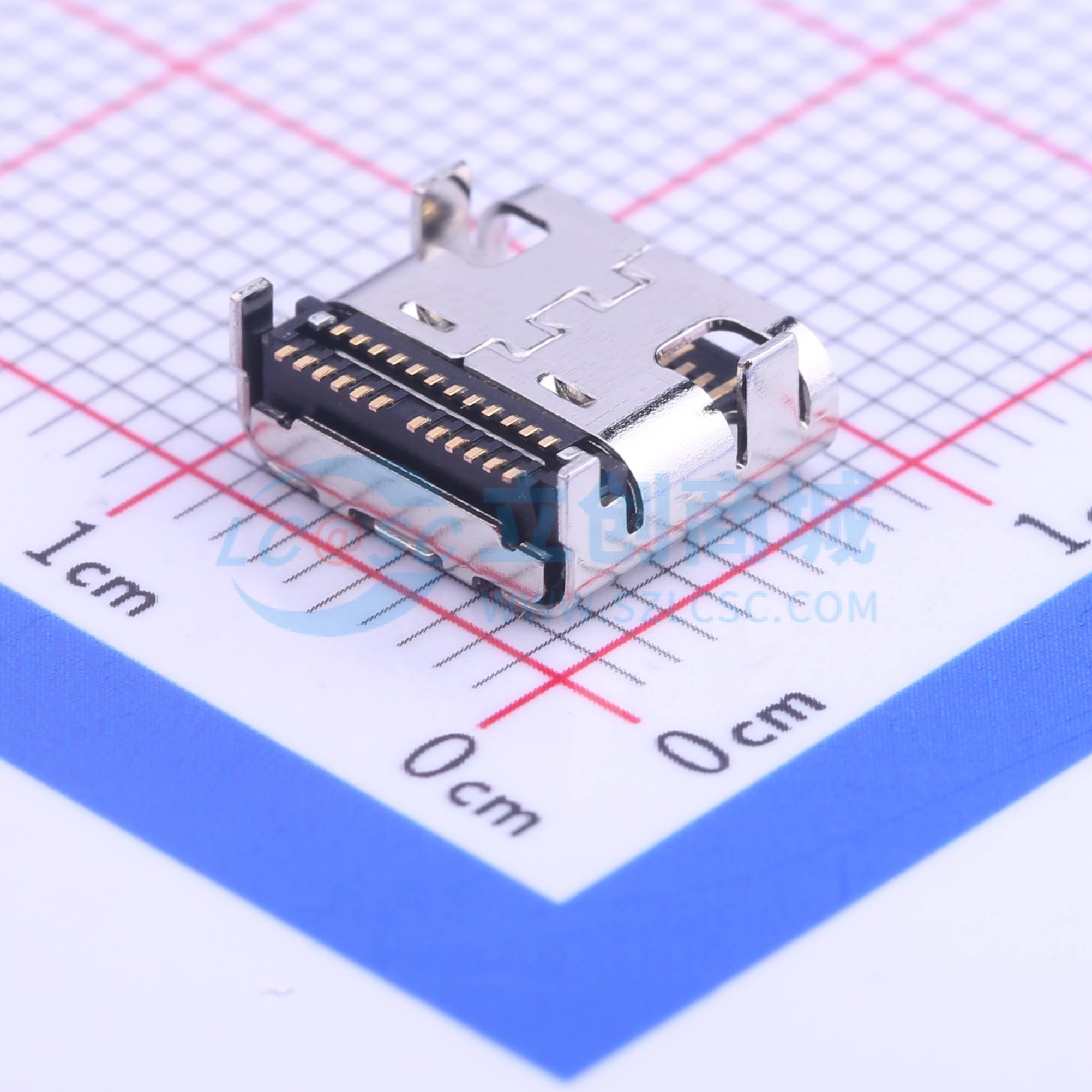
Figure 9 shows the USB 3.0-TYPE-C interface.
The changes between the TYPE-B interface and the 2.0 protocol are very obvious, so you generally won't buy the wrong one. Soldering and wiring are also relatively easier. This design uses the USB 3.0-TYPE-B interface.

Figure 10 shows the USB 2.0-TYPE-B interface.

Figure 11 shows the USB 3.0-TYPE-B interface.
In the input interface circuit, the corresponding pins are brought out. For better anti-interference, a 100nF capacitor is generally connected in series in the USB 3.0 transmit differential data lines for filtering. At the same time, to prevent electrostatic damage to the chip and the inserted device, a TVS diode is added to the input section for protection.

Figure 12 Input Interface Circuit
7. Output Interface:
Use TYPE-A female connector for extended output. Note that TYPE-A interfaces also have USB 2.0 and USB 3.0 protocols. When selecting components, pay attention to this and refer to the corresponding component datasheet. TYPE-A female connector 2.0 interface generally has 4 pins, while 3.0 interface generally has 9 pins.
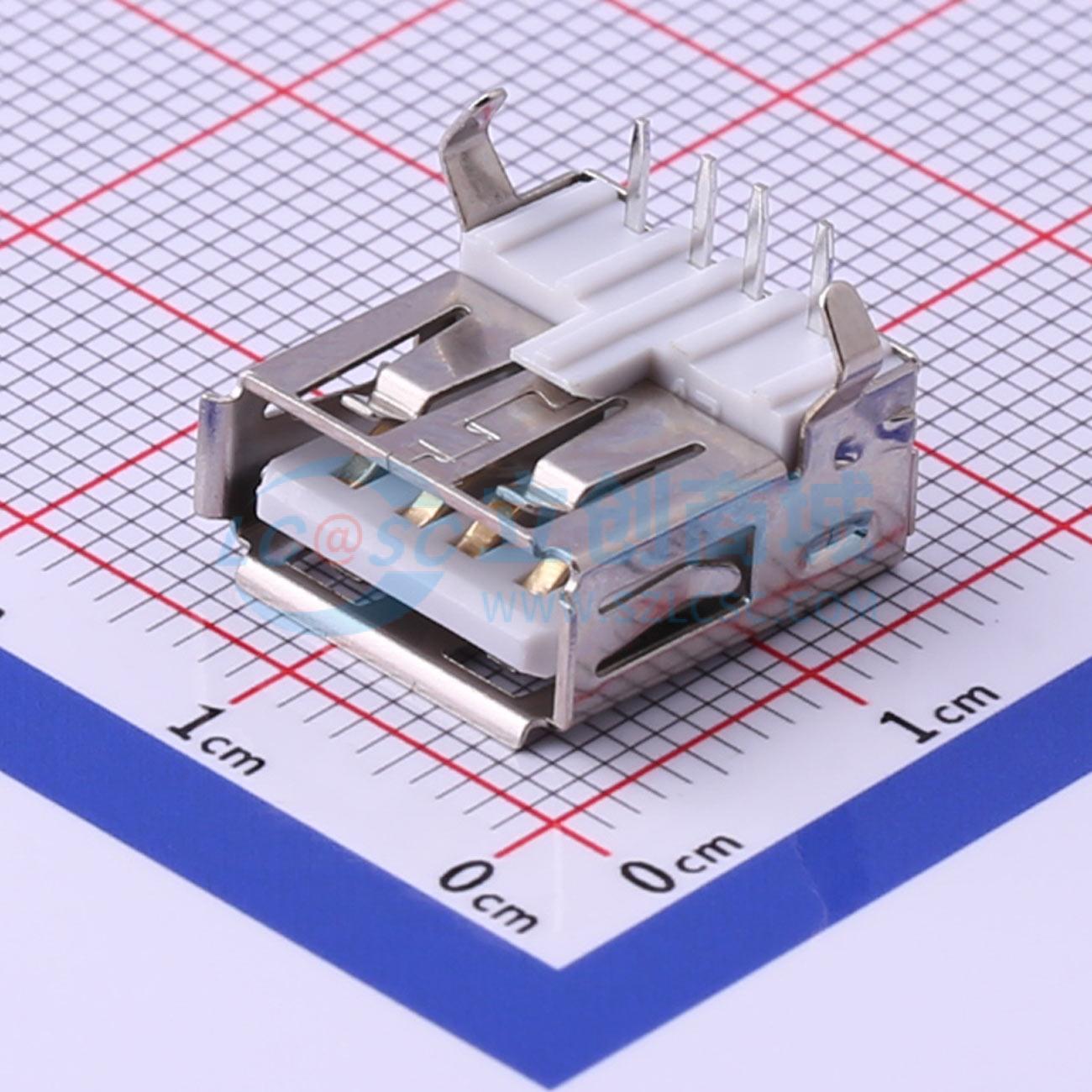
Figure 13 USB 2.0-TYPE-A Interface
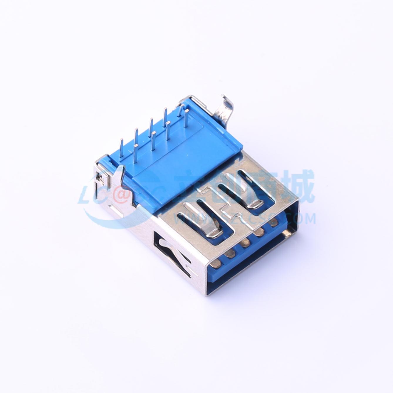
Figure 14 USB 3.0-TYPE-A Interface
After selecting the appropriate components according to requirements, add filter capacitors and TVS diodes for protection. The chip has four outputs; you can draw one first and then copy the remaining three.
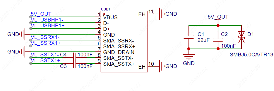
Figure 15 USB 3.0 Output Interface Circuit
IV. PCB Design
1. PCB Layout
The USB interface should be placed close to the board edge or structurally positioned for easy insertion and removal;
the TVS diode should be close to the USB interface, and it is recommended that the power line enter the TVS diode immediately upon exiting to provide protection;
when laying out, the distance between the chip and the interface should be considered, and they should not be too far apart, shortening the differential line distance;

Figure 16 PCB Layout Diagram
2. PCB Routing
USB signals should be routed as differential lines, with an impedance control of 90 ohms, and grounded out. The length of high-speed differential lines should preferably not exceed 1800mil;
when routing, prioritize high-speed differential signal lines, and avoid changing layers as much as possible. When changing layers, add return ground vias;
the length error of differential pairs should be as small as possible, preferably within 5mil;

Figure 17 Top Layer Routing Diagram
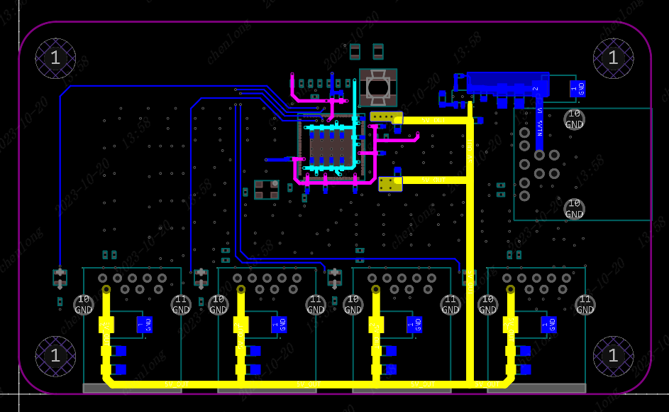
Figure 18
3. Design Optimization
: Remove isolated copper traces;
appropriately wrap ground planes; increase
silkscreen size (ideally 40mil or larger);
add JLCJLCJLCJLC silkscreen markings in suitable areas for a more aesthetically pleasing finished product;
V. Precautions:
Impedance calculation can be done using the impedance calculation tool available on the JLCPCB website;
power traces need to consider the actual current; this project limits it to 1A, so if the current increases later, the power traces need to be enlarged;
during soldering, it is recommended to use a hot air gun or heating plate to solder the main control chip first, and after soldering, use a multimeter to check for cold solder joints or short circuits;
VI. Video Explanation:
3.0 Hub Design Overview
https://www.bilibili.com/video/BV1nj411v7Lu/
VL812 Chip Circuit Design
https://www.bilibili.com/video/BV1j8411r7Ld
VL812 Peripheral Circuit Design:
https://www.bilibili.com/video/BV18H4y197cR
PCB Layout and Design Techniques
: https://www.bilibili.com/video/BV1Ah4y1i7iJ
PCB Routing Techniques
: https://www.bilibili.com/video/BV18h4y1i7gu
PCB Optimization and Free Ordering Techniques:
https://www.bilibili.com/video/BV1Zc411o7zb
VII. Physical Demonstration and Testing


 京公网安备 11010802033920号

 XC6116A024


