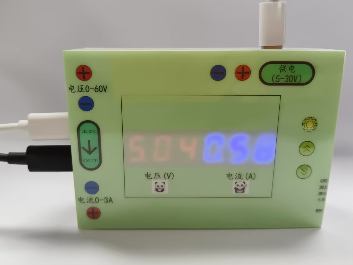
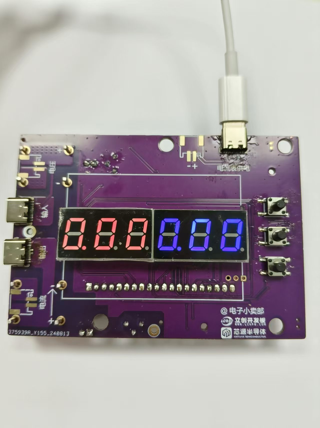
I. Physical Demonstration:
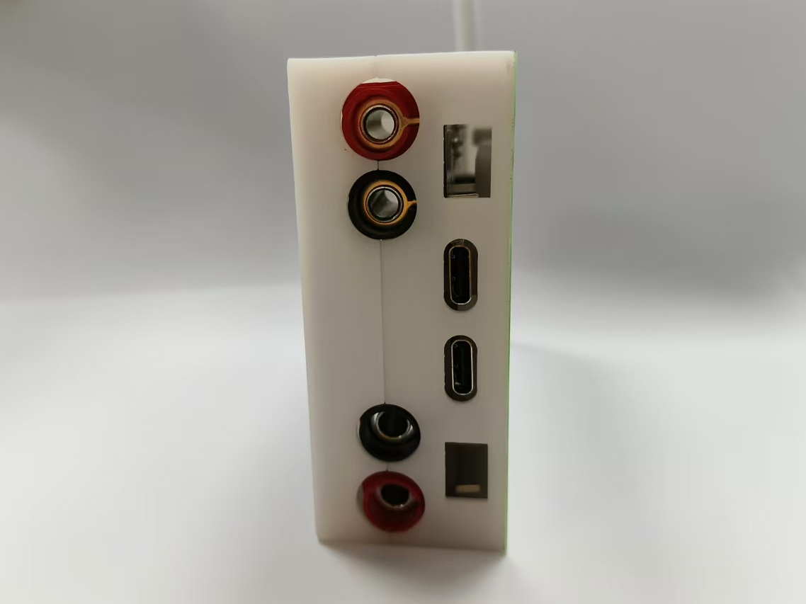
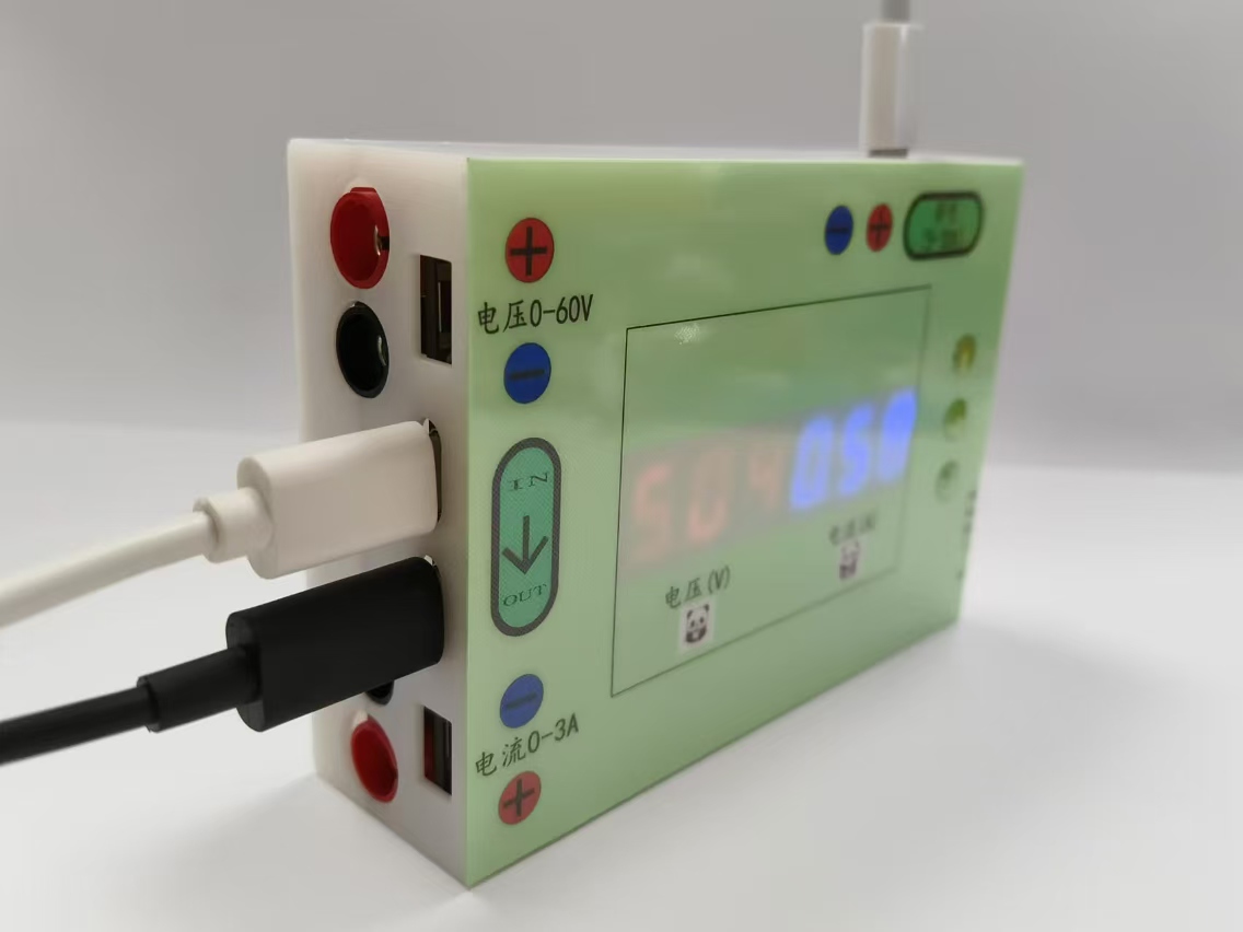
3D rendering and
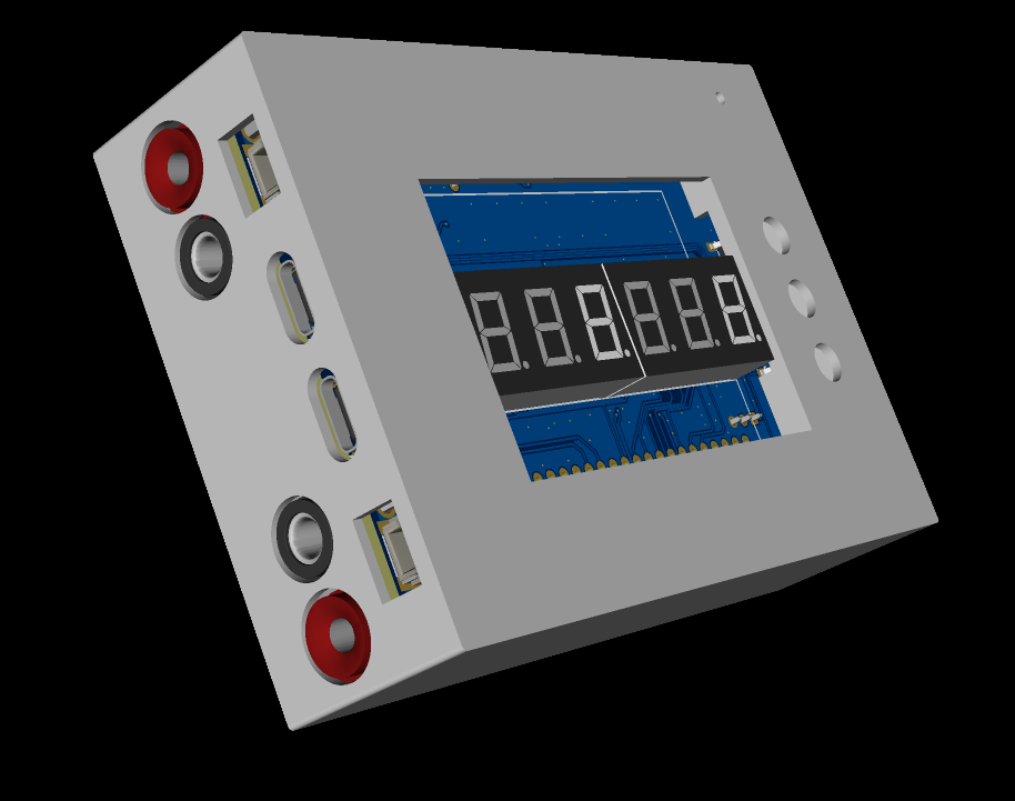

physical image.

II. Design Summary:
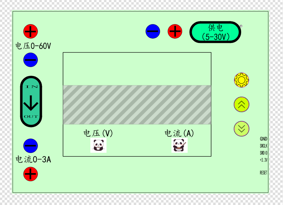
This project uses the LCSC CW32F030C8Tx development board (core board) as the main controller, capable of simultaneously displaying voltage and current. The display uses two 3-digit LED displays to show voltage and current respectively, and a reserved SPI LCD screen interface is provided. Power is supplied via a TYPE-C interface, with a reserved 2-pin connector. The measurement interface uses four banana plugs to measure voltage and current respectively, with TYPE-C input and output. Note that TYPE-C and banana plugs cannot be connected to an external power supply simultaneously. When testing current, pay attention to the current direction and use the lower end for measurement. If voltage and current cannot be measured using TYPE-C, reverse one end of the TYPE-C connector. The ammeter has a calibration function; using a higher-digit measuring instrument for calibration will result in smaller measurement errors.
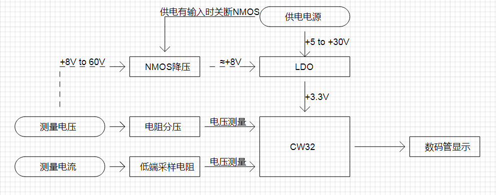
III. Overall Design Block Diagram
IV. Partial Hardware Circuit Description
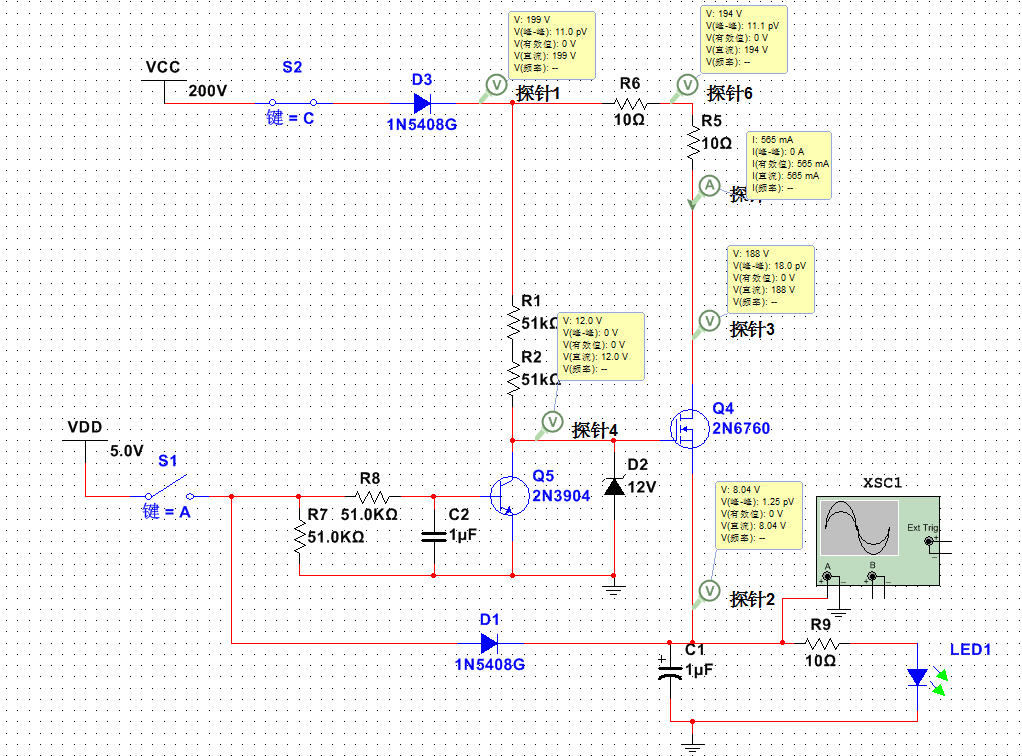
Simulation diagram of power supply to the system from the voltage measurement terminal. When the measured voltage is greater than 8V and can output a certain current capability, a separate power supply to the ammeter is not required. The higher the input voltage, the higher the power consumption of the NMOS; pay attention to heat dissipation. The VDS should be selected with a relatively large voltage drop. For safety, it is recommended that the measured voltage not exceed 60V.
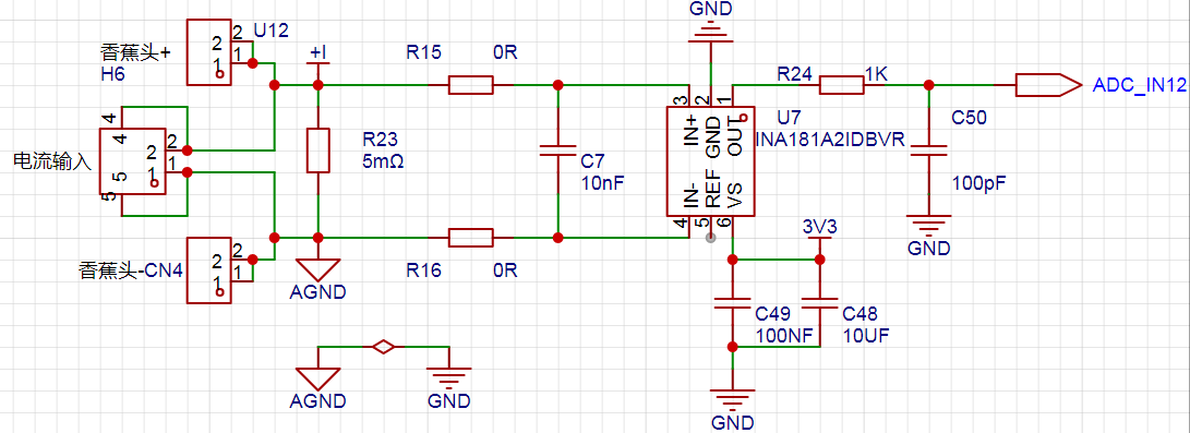
A smaller resistor should be used at the current sampling terminal to minimize current loss. The INA181A2 provides a fixed voltage amplification of 50 times, and the ADC reads the amplified voltage to calculate the theoretical current value.
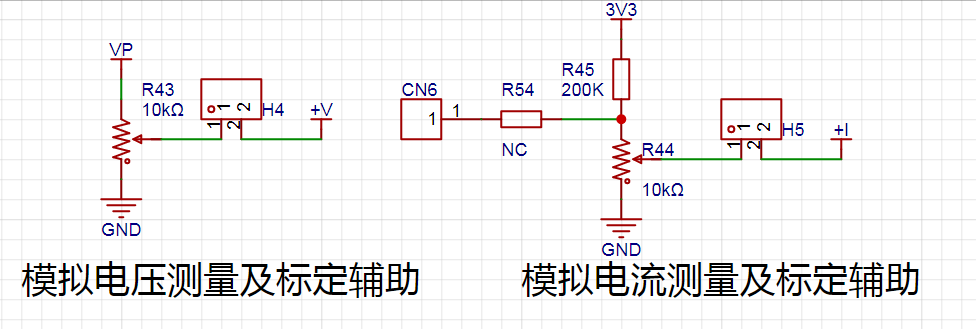
This is the interface for voltage calibration and analog current calibration. Do not short-circuit H4 and H5 during normal use. When there are no multiple power supplies and electronic loads, the analog current calibration method can be used.
Analog voltage calibration method: Power the current source with a power supply greater than 15V, short-circuit H4, and use a calibrated multimeter to measure the voltage ports (V+, GND). When adjusting the sliding resistor, the multimeter should be in the 5V or 15V calibration voltage range. The ammeter should be calibrated in mode 1 or mode 2.
Analog Current Calibration Method: The method for detecting current is actually to measure the voltage across the sampling resistor. Calibration can be performed by specifying a voltage value to the microcontroller's ADC port. Remove the sampling resistor, short-circuit H5, and use a multimeter to measure the voltage at the ADC_IN12 port. Adjust the sliding resistor to achieve the specified voltage and enter calibration mode. In Mode 3 calibration at 0.5A, the multimeter reading is 0.005Ω = 0.125V. In Mode 3 calibration at 1.5A, the multimeter reading is 0.005Ω = 0.375V.
The demonstration video shows actual voltage and current calibration, not analog calibration.
Actual Voltage Calibration Method: Disconnect H4 and H5, power on normally, and input the specified voltage value at the voltage measurement terminal to enter calibration mode. Actual Current Calibration Method:
Disconnect H4 and H5, power on normally, connect the current measurement terminal in series with the load (low-side detection), and apply a constant current of 0.5A or 1.5A to the electronic load to enter calibration mode.
V. Program Description
and Tips: Please include the program flowchart and upload the source code in the attachment.
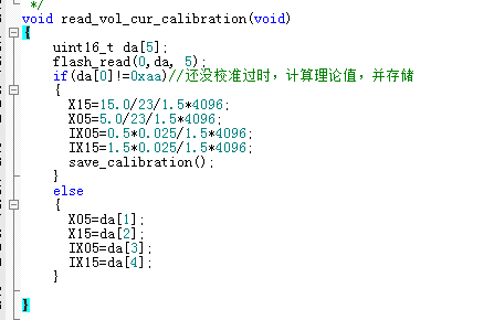
The voltage and current values read before calibration are theoretical values; due to hardware errors, calibration will provide greater accuracy. X15 is the voltage read after a 15V input voltage is divided by a 22K and a 1K resistor; the reference voltage is 1.5V. The 12-bit ADC is 4096. IX05 is for an input current of 0.5A, a sampling resistor of 0.005R, and amplified 50 times to 0.025.
VI. Precautions:
Do not reverse the voltage or current connections. For current measurement, connect the positive terminal of the ammeter to the negative terminal of the load being measured, and connect the negative terminal of the ammeter to GND.

Do not use the TYPE-C measurement port and the banana plug measurement port simultaneously.
VII. Calibration Method:
Use a higher-precision instrument as a reference during calibration.
This ammeter defines 5 operating modes; the K1 key is used to switch display modes. Press and hold the K1 key for 3 seconds to set the parameter value for the corresponding mode and save it to FLASH.
Mode 0: Displays normal voltage and current values (the upper row of digital tubes displays the voltage value in .V or .V automatically, the lower row displays the current value in _.**A).
Mode 1: 5V voltage calibration setting. The upper row of digital tubes displays 5.05. The lower row displays the current voltage value in _.V or ._V. In this mode, the multimeter should be set to 5.00V when measuring the measured bit. Press and hold the K1 key for 3 seconds to calibrate the current value to 5V.
Mode 2: 15V voltage calibration setting. The upper row of digital tubes displays 5.15. The lower row displays the current voltage value in _.V or ._V. In this mode, the multimeter should be set to 15.0V when measuring the measured bit. Press and hold the K1 key for 3 seconds to calibrate the current value to 15V.
Mode 3: 0.5A current calibration setting. The upper row of digital tubes displays A.0.5. The next row displays the current current value _.**A. Press and hold the K1 key for 3 seconds to calibrate the current value to 0.5A.
Mode 4: Current 1.5A calibration value setting. The previous row of the digital tube displays A.1.5. The next row displays the current current value *.**A. Press and hold the K1 key for 3 seconds to calibrate the current value to 1.5A.
VIII. Calibration Demonstration Video
Voltage Calibration Demonstration (External voltage calibration, do not short-circuit terminals H4 and H5)
Current Calibration Demonstration (External constant current source calibration, do not short-circuit terminals H4 and H5)


 京公网安备 11010802033920号

 507-146Z251-2E


