I. Physical Display and Partial Manufacturing Process Demonstration:


Physical Display Link: Demonstration Video
II. Detailed Functional Description
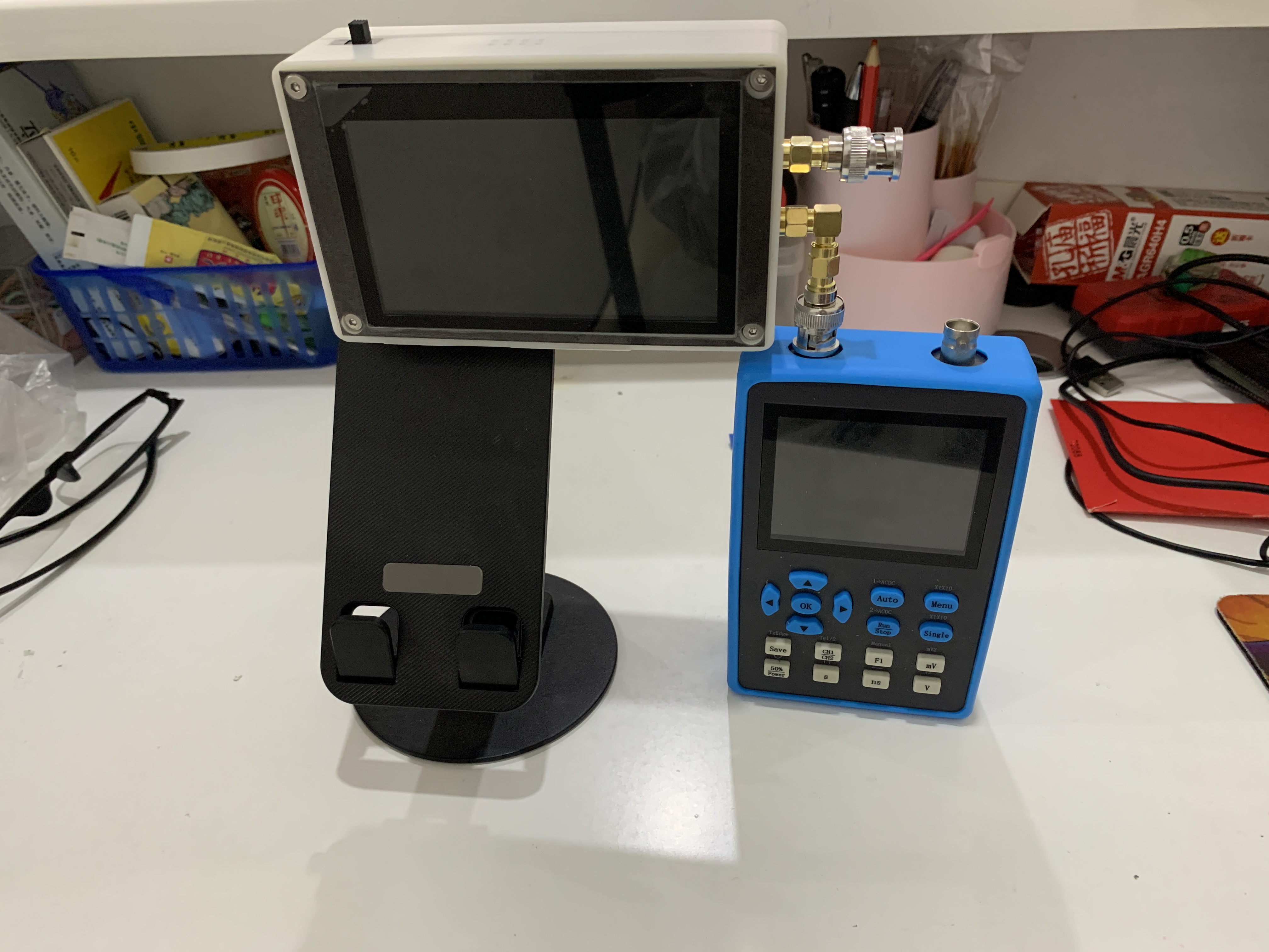
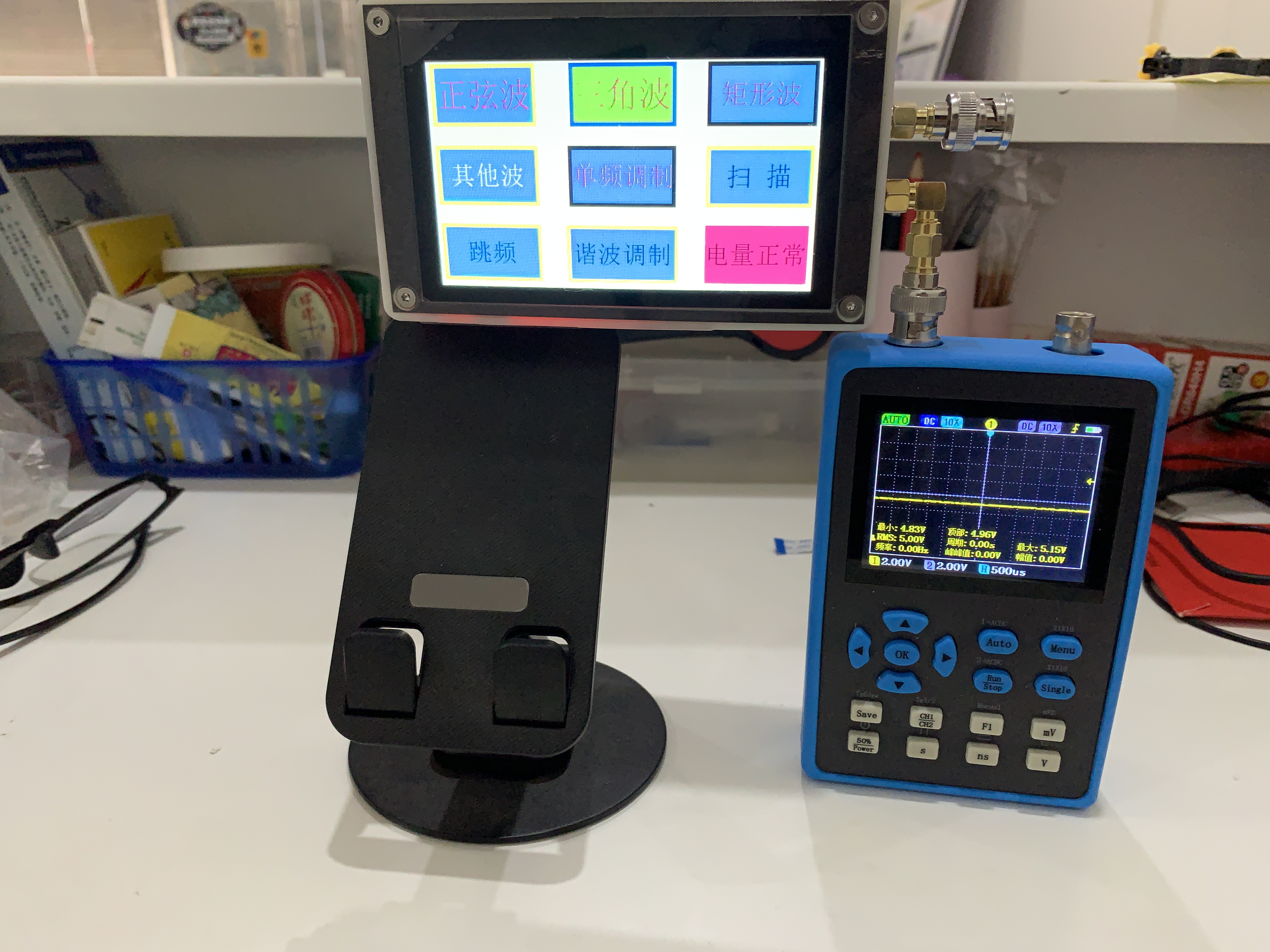
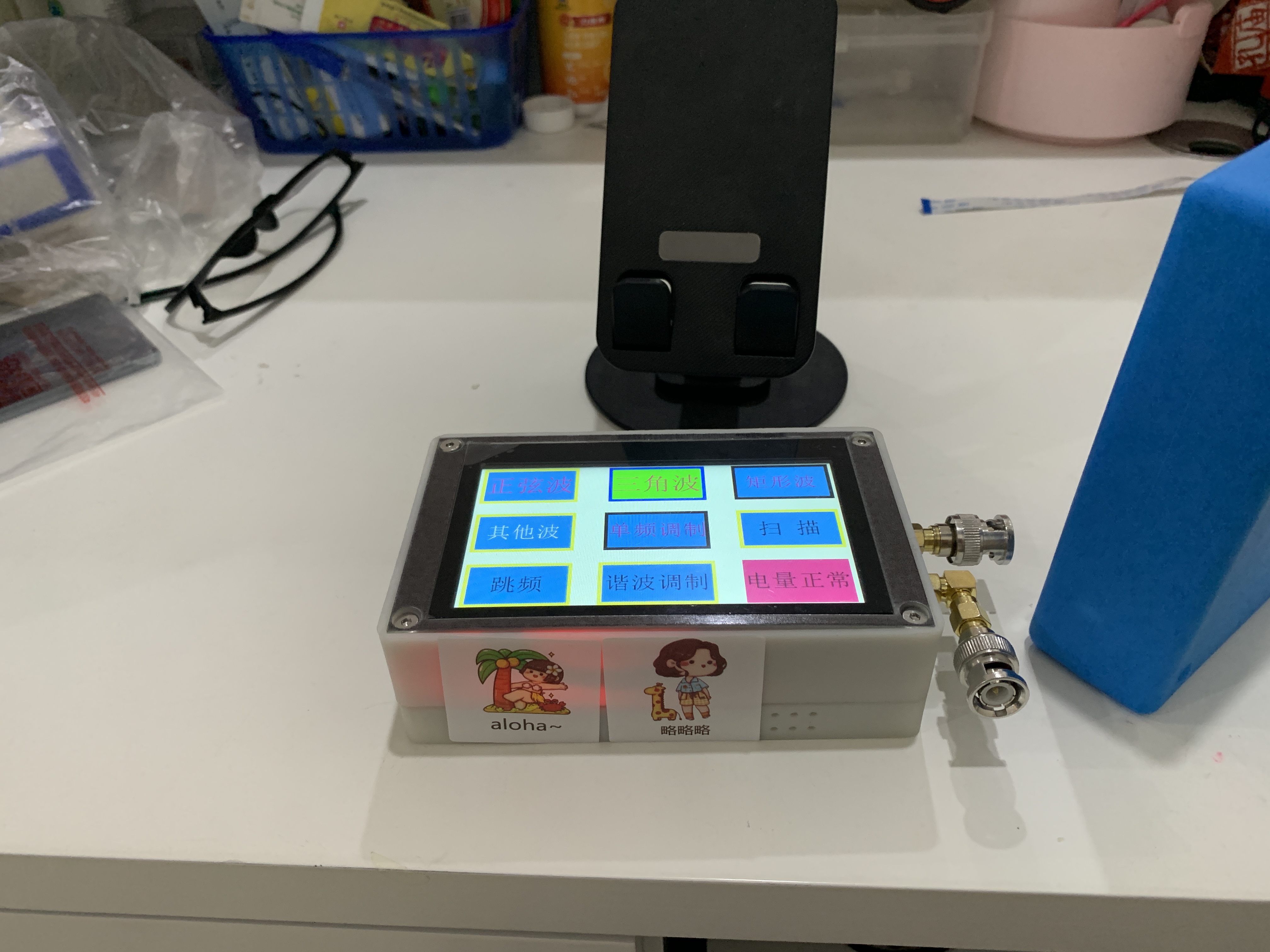
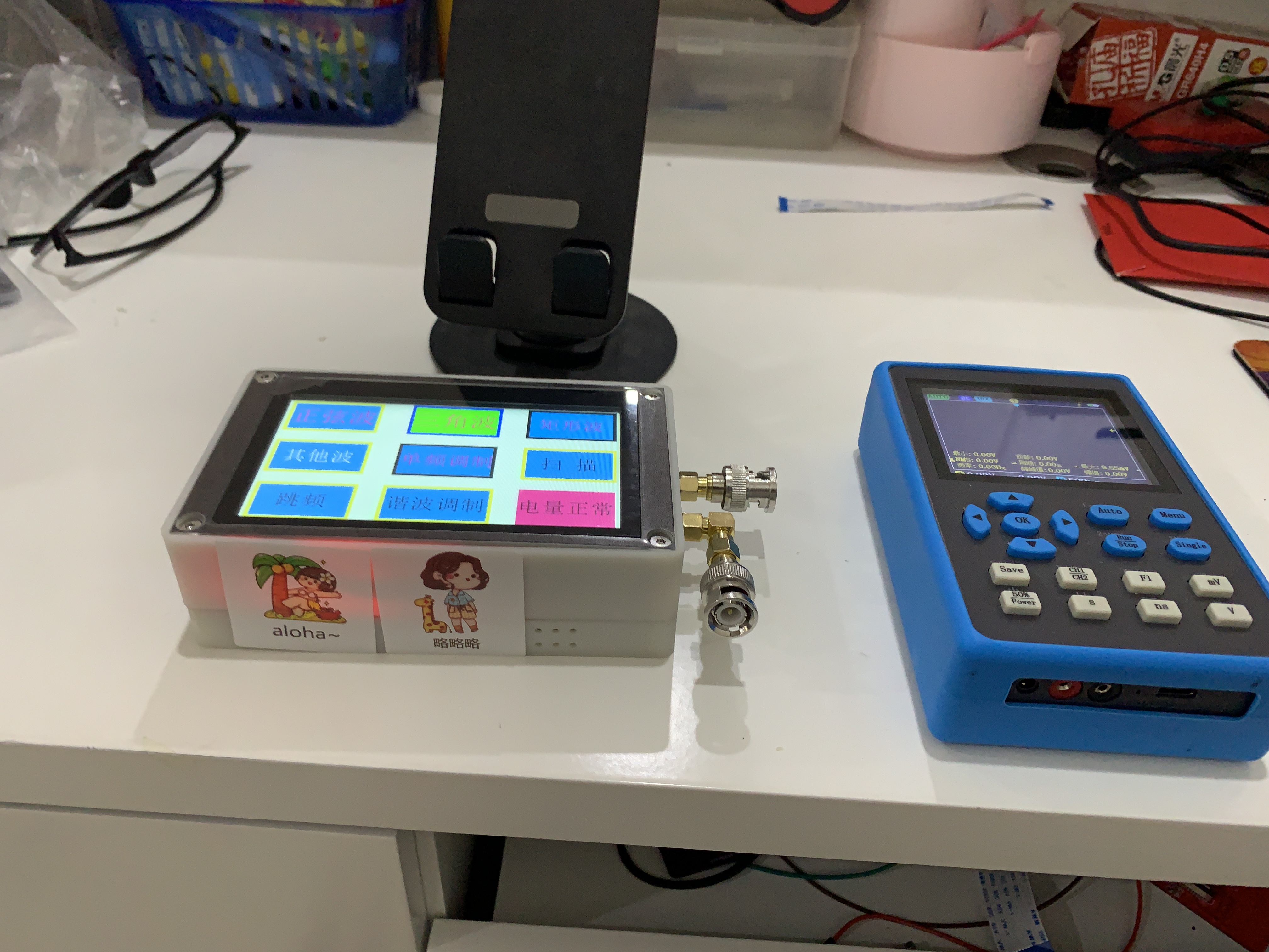
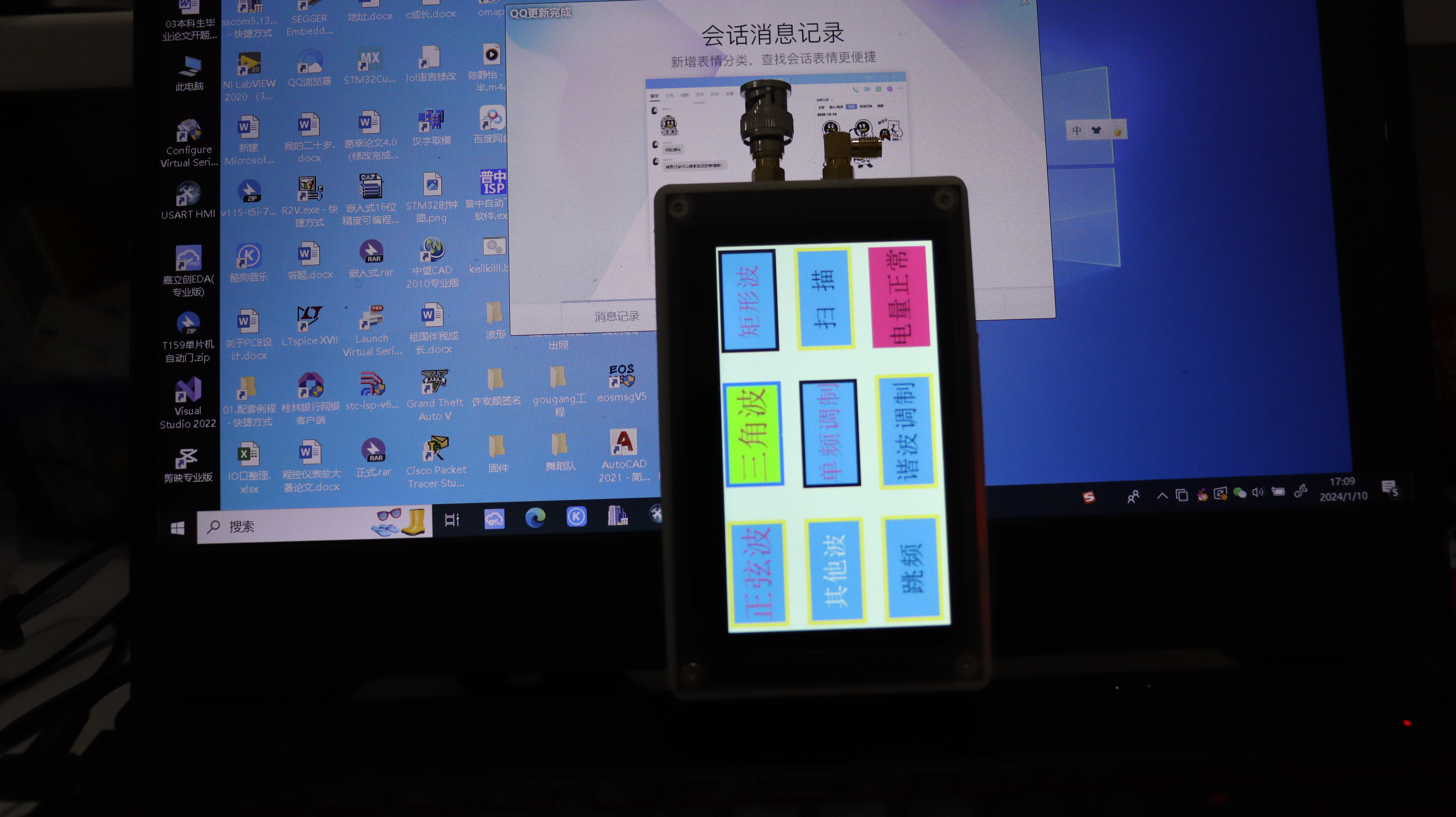
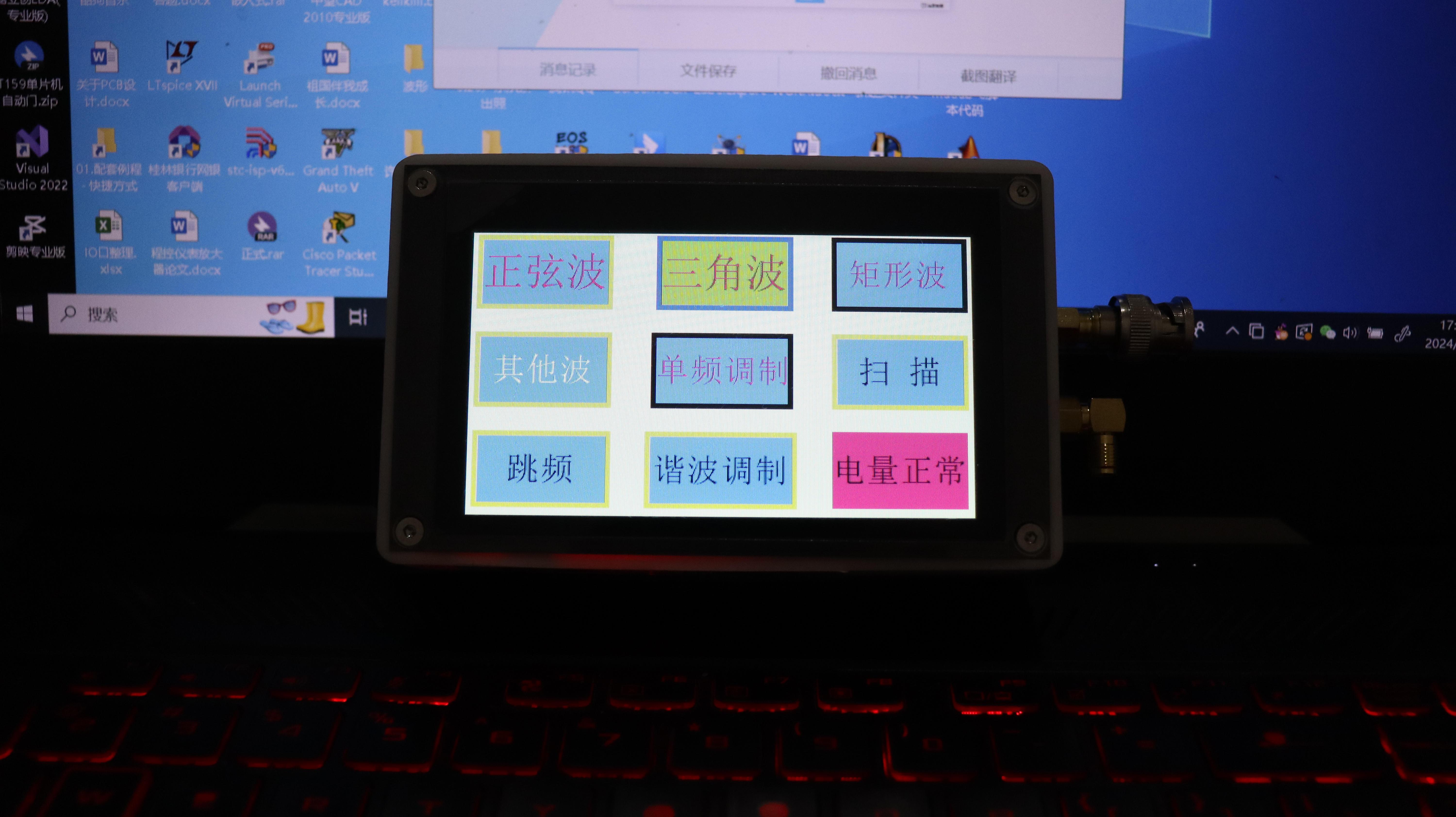
This design uses the CW32F030 series microcontroller as the system control core, the AD9910 module as the waveform generation system, the HMI 4.3-inch touchscreen as the human-machine interface for setting relevant parameters, and the W25Q64 as the data storage device. With a simple peripheral circuit structure, a multi-functional function signal generator is designed. The basic function GUI interface is shown in the figure.

The basic functions of the project include:
1. 1-420MHz sine wave output.
2. 3.7-244kHz triangular wave output. 3.
3.7-244kHz square wave output.
4. Other common wave outputs (14 other common waveforms).
5. Single frequency modulation can select the following functions:
(1) AM modulation.
(2) PM modulation.
(3) FM modulation.
(4) 2ASK.
(5) 2PSK.
(6) 2FSK.
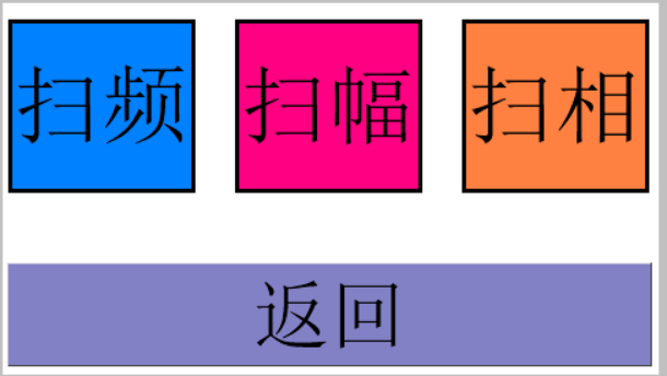
6. Scanning function can select the following functions:
(1) frequency sweep.
(2) amplitude sweep.
(3) phase sweep.
7. Harmonic modulation can select the following functions:
(1) FM.
(2) AM.
(3) PM.
8. Frequency hopping (this function is not yet implemented).
8. Other (extended functions).
Detailed function description:
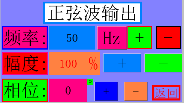
1. Sine Wave Output Mode: In sine wave output mode, frequency, amplitude, and phase are adjustable via the HMI touchscreen. Frequency range: 1Hz-450MHz, 1Hz step; amplitude: 0-100%, 1% step; phase: 0-360 degrees, 1 degree step. The GUI interface is shown in the figure below.
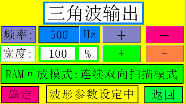
2. Triangle Wave Output Mode: In triangle wave mode, frequency and width are adjustable, with a frequency step of 1Hz and a maximum of 244kHz. Two waveform output modes are provided:
1. Continuous Bidirectional Scan: After playing a waveform, the waveform is played in reverse.
2. Continuous Loop Scan: Continuously plays a waveform.
The GUI interface is shown in the figure below.
3. Square Wave Output Mode: In square wave output mode, waveform width and frequency are adjustable, with a width step of 5% and a frequency step of 1Hz.
The GUI interface is shown in Figure

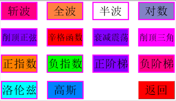
4. Other waveform output modes: The output waveform has the following 14 common waveforms to choose from:
(1) Chopper.
(2) Full wave.
(3) Half wave.
(4) Logarithmic.
(5) Clipped sine.
(6) Singer function.
(7) Damped oscillation.
(8) Clipped triangle.
(9) Positive exponential.
(10) Negative exponential.
(11) Positive step.
(12) Negative step.
(13) Lorentz.
(14) Gaussian.
The GUI interface is shown in Figure
4. In this mode, the waveform frequency and waveform output mode are adjustable. Two waveform output modes are provided:
1. Continuous bidirectional scanning
2. Continuous cyclic scanning
The corresponding waveform output interface is shown in Figure 4.
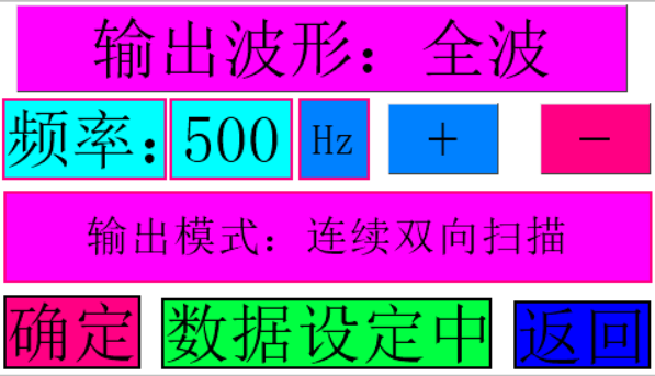
By clicking the output waveform button, you can switch between one waveform output in sequence.
Waveform output can be performed by clicking the confirmation button. After pressing the confirmation button, pressing it again will become the cancel button, canceling the waveform output. Pressing the return button will return to the previous menu.
4. Single-frequency modulation GUI is shown in the figure below.
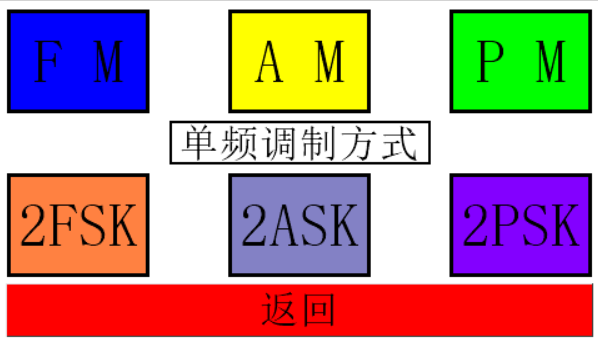
4. Single-frequency modulation mode provides
(1) FM modulation:
The interface GUI is shown in the figure below.
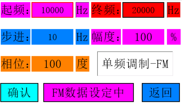
In this mode, the following parameters of FM modulation can be set:
1. Start frequency.
2. End frequency.
3. Step frequency.
4. Waveform amplitude.
5. Waveform phase.
(2) AM modulation
GUI is shown in the figure below.
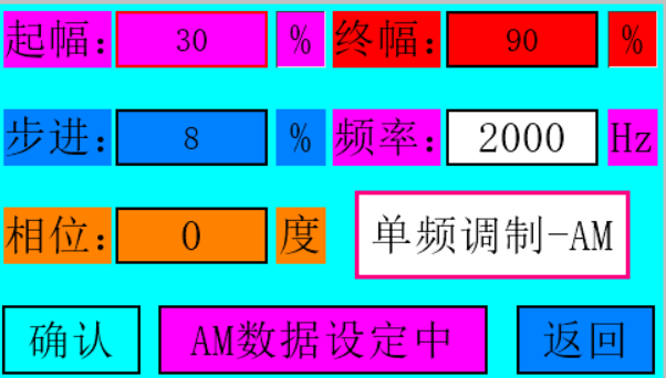
In this mode, the following parameters of AM modulation can be set:
1. Start amplitude.
2. End amplitude. 3.
Step amplitude.
4. Waveform frequency.
5. Waveform phase.
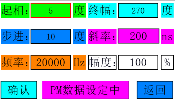
(3) PM modulation
GUI is shown in the figure below

. In this mode, the following parameters of PM modulation can be set:
1. Start phase.
2. End phase.
3. Step phase.
4. Waveform frequency.
5. Waveform amplitude.
(4) 2FSK modulation
GUI is shown in the figure below
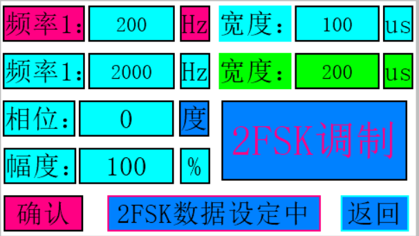
. In this mode, the following parameters of 2FSK modulation can be set:
1. Start frequency.
2. End frequency.
3. Start frequency duration.
4. Start frequency duration.
5. Waveform amplitude.
5. Waveform phase.
(5) 2ASK modulation
GUI is shown in the figure below.
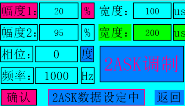
In this mode, the following parameters of 2ASK modulation can be set:
1. Start amplitude.
2. End amplitude.
3. Start amplitude duration.
4. Start amplitude duration.
5. Waveform frequency.
5. Waveform phase.
(5) 2PSK modulation
GUI is shown in the figure below.

In this mode, the following parameters of 2PSK modulation can be set:
1. Start phase.
2. End phase.
3. Start phase duration.
4. Start phase duration.
5. Waveform frequency. 5.
Waveform amplitude.
4. Scan mode GUI is shown in the figure below.
Scan mode function 1: frequency
sweep. The three different frequency sweep modes GUIs under the frequency sweep function are shown in the figure below. Upper frequency
sweep GUI

Lower frequency sweep GUI
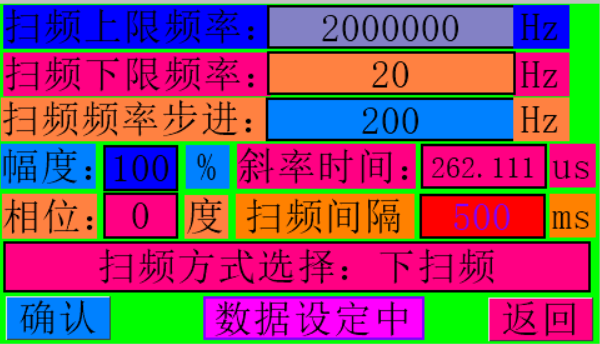

In frequency sweep mode, the following parameters can be set for frequency sweep control:
1. Upper sweep frequency limit
2. Lower sweep frequency limit
3. Sweep step
frequency
4. Sweep amplitude 5. Sweep
phase 6. Sweep time interval
7. Sweep DRC pin time interval
8. Lower sweep frequency limit
9. Select sweep mode: upper sweep, lower sweep, upper and lower sweep.
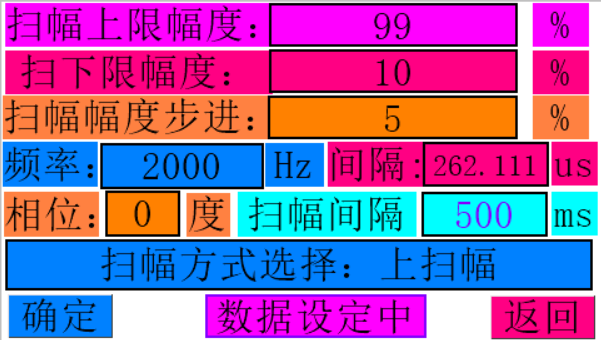
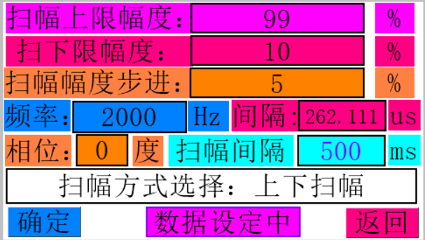
Function 2: Amplitude Sweep . The amplitude sweep function GUI
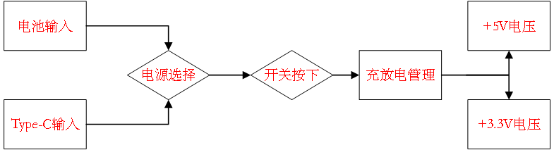
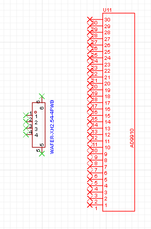
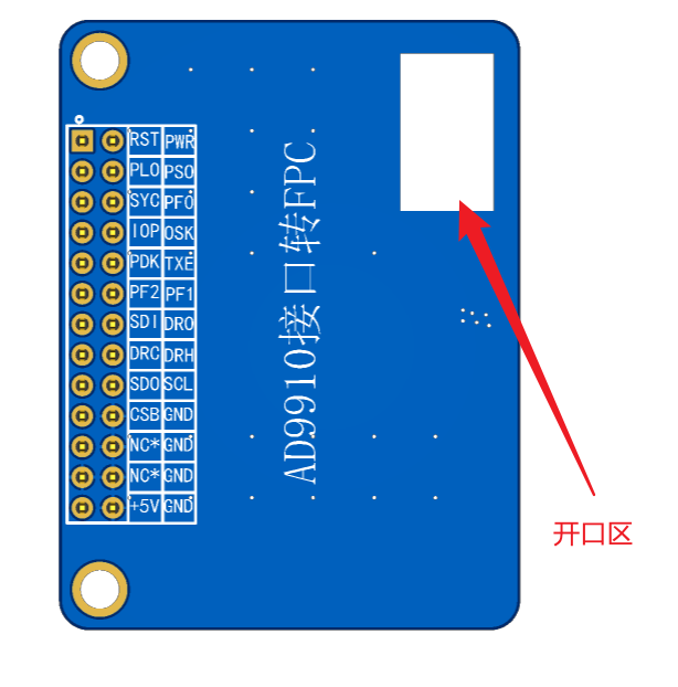
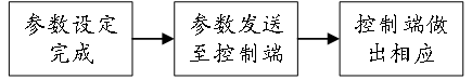
is shown in the figure below . In amplitude sweep mode, the following parameters can be set for amplitude control: 1. Upper sweep amplitude limit 2. Lower sweep amplitude limit 3. Sweep step amplitude 4. Sweep frequency 5. Sweep phase 6. Sweep time interval 7. Sweep DRC pin time interval 9. Select sweep mode: upper sweep, lower sweep, upper and lower sweep. Function 3: Phase Sweep . The phase sweep function GUI is shown in the figure below . In phase sweep mode, the following parameters can be set for phase control: 1. Upper limit amplitude of phase sweep 2. Lower limit amplitude of phase sweep 3. Phase sweep step amplitude 4. Sweep frequency 5. Phase sweep phase 6. Phase sweep time interval 7. Phase sweep DRC pin time interval 9. Select sweep mode: upper sweep, lower sweep, upper and lower sweep Harmonic modulation function Harmonic modulation GUI is shown in the figure below: Harmonic modulation function 1: FM modulation Harmonic FM modulation GUI is shown in the figure below: In this mode, the following parameters can be set for FM modulation 1. FM modulation start frequency 2. FM modulation end frequency 3. FM modulation amplitude 4. FM modulation phase 5. FM modulation slope sustain time Harmonic modulation function 2: AM modulation Harmonic AM modulation GUI is shown in the figure below: In this mode, the following parameters can be set for AM modulation 1. AM modulation start amplitude 2. AM modulation end amplitude 3. AM modulation frequency 4. AM modulation phase 5. AM modulation slope sustain time Harmonic modulation function 3: The PM modulation harmonic AM modulation GUI is shown in the figure below. In this mode, the following parameters can be set for PM modulation: 1. PM modulation start phase; 2. PM modulation end phase; 3. PM modulation frequency; 4. PM modulation amplitude; 5. PM modulation slope and duration. III. Hardware Design Description This project mainly consists of a CW32F030 microcontroller, an AD9910 module, a 4.3-inch HMI touchscreen, and a W25Q64 memory chip. The hardware does not contain complex digital or analog circuits; the most complex part is the AD9910 control board circuit. Detailed explanations can be found in other open-source projects under this account. The CW32 has few GPIO ports but relatively powerful functions, performing all functions except frequency hopping. Therefore, the hardware circuit will not be described in detail. The entire hardware system can be understood as: a CW32 minimum system (small blue board) + an HMI touch screen + an AD9910. The most difficult part is in the software code design. For ASK, PSK, FSK, AM, PM, FM, amplitude sweep, frequency sweep, and phase sweep, a deep understanding of high-frequency electronics and a certain awareness of practical applications are required... I don't know how to explain it, for example, determining the capacitance of a capacitor through frequency sweep... For specific implementation principles... please refer to relevant materials. A brief explanation of the power supply section of the hardware circuit: The power supply circuit of this project consists of a Type-C circuit and a battery power supply circuit. When the Type-C is floating, the battery provides power; when the Type-C interface is connected, the Type-C provides system power. The flowchart is shown below. The circuit structure is shown below . Power flow: from left to right. The circuit structure contains circuits that shield all interfaces; these are used for positioning hole drawing and 3D model drawing, and have no electrical significance in the actual circuit. For detailed circuitry information regarding the AD9910, please refer to my other open-source projects; it will not be discussed extensively here. The schematic for this project is very simple; the only complex part is the power supply circuit. The PCB design involves only two PCBs: the core board and an adapter board for the AD9910 interface. This adapter board converts the 2.54mm header connector to a PFC connector for connection to the FPC interface on the core board, forming an integrated system and avoiding the need for wire harness connections. An opening is created on this PCB to route the FPC cable. To reduce the board's actual height, it is designed to be as thin as possible; therefore, a thickness of 1.2mm was chosen during board fabrication. A large cutout area is created in the center of the main board to house the AD9910. The AD9910 can be perfectly secured using the cutout area and bottom screw posts. For cost-saving purposes, this part can be omitted; the bottom screw posts are sufficient for fixation. Boards larger than 10x10mm cannot use free PCB fabrication; double-layer boards cost over 40 yuan! III. Software Design Description: The software is the final step in the entire design. Hardware circuit design took an afternoon and over a month, involving many aspects. The software operation flow is shown in the following diagram. 4.3-inch HMI serial port screen code writing. The serial communication code flow is shown in the following diagram . The serial port screen operation flow is shown in the following diagram. All logic code follows the following principles: Due to limitations of the CW32's on-chip resources, some powerful RGB screens cannot be used. Therefore, the HMI serial port screen is selected for human-computer interaction. Experimental results show that the human-computer interaction is good and basically achieves the intended functions. The HMI serial port screen is only used to send data with a predetermined frame structure. The microcontroller performs the calculation and responds accordingly. The microcontroller does not perform any other control on the HMI serial port screen.


The serial port screen frame structure is shown in the figure below:

Frame structure composition: Frame header + 4-bit control data + Frame tail (0A + data bit or flag bit 1 + data bit or flag bit 2 + data bit or flag bit 3 + data bit or flag bit 3 + Frame tail)
Frame header: 0A, data reception enable flag
Data: composed of parameters set on the screen, maximum 4 bits
Frame tail: A0, data reception end flag
For example, if a frequency parameter is sent, the frame structure sent by the HMI is: 0A EF 1A 03 06 A0. The microcontroller receives the data, and the control system response flow is shown in the figure below.

For specific logic code, please refer to the uploaded HMI project. This module is easy to learn. When programming it, I could only draw stick figures, so the UI interface wasn't very nice, but the code logic was very complete.
In the LCD display part, you can understand it as what data you want to send, when to send it, and what happens after it's sent!
2. W25Q64 Code Development
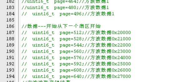
: Due to the CW32 on-chip Flash issue, I could only use the W25Q64 for waveform data storage. Under the CW32, only a single 4096-byte data segment can be defined. Therefore, I had to write 4096 waveform data segments to the corresponding 4KB sector at a time.
When using the W25Q64, it's crucial to specify:
1. Which block (64 bytes per block) of 128 blocks to store the data in. Which sector (32KB), which region (4KB), and which page (256 bytes) address within that region.
This project uses linear storage, storing 4096 data segments at a time, equivalent to storing one region at a time. A 32KB sector can store 8 waveforms, and a 64KB block can store 16 waveforms. Therefore, approximately 3 blocks are needed for data storage. The storage structure is shown in the diagram below.

The waveform writing steps are shown in the figure below:

1. Store the waveform data in an array of size 4096: const uint8_t Wave_Date[4096]

2. Select the 4K sector to be written, represented by a decimal number, starting from 0 and incrementing upwards
. 3. Run the writing code to split the 4096-sized waveform data into 256-sized segments and write them in pages, which can just fill a 4K sector. The code is shown below.
for(i=0;i<256;i++) {Wdate[i]=Wave_Date[i];} W25Q64_PageWrite(Wdate,0+page);
for(i=0;i<256;i++) {Wdate[i]=Wave_Date[i+256];} W25Q64_PageWrite(Wdate,1+page);
for(i=0;i<256;i++) {Wdate[i]=Wave_Date[i+256*2];} W25Q64_PageWrite(Wdate,2+page);
for(i=0;i<256;i++) {Wdate[i]=Wave_Date[i+256*3];} W25Q64_PageWrite(Wdate,3+page);
for(i=0;i<256;i++) {Wdate[i]=Wave_Date[i+256*4];} W25Q64_PageWrite(Wdate,4+page);
for(i=0;i<256;i++) {Wdate[i]=Wave_Date[i+256*5];} W25Q64_PageWrite(Wdate,5+page);
for(i=0;i<256;i++) {Wdate[i]=Wave_Date[i+256*6];} W25Q64_PageWrite(Wdate,6+page);
for(i=0;i<256;i++) {Wdate[i]=Wave_Date[i+256*7];} W25Q64_PageWrite(Wdate,7+page);
for(i=0;i<256;i++) {Wdate[i]=Wave_Date[i+256*8];} W25Q64_PageWrite(Wdate,8+page);
for(i=0;i<256;i++) {Wdate[i]=Wave_Date[i+256*9];} W25Q64_PageWrite(Wdate,9+page);
for(i=0;i<256;i++) {Wdate[i]=Wave_Date[i+256*10];} W25Q64_PageWrite(Wdate,10+page);
for(i=0;i<256;i++) {Wdate[i]=Wave_Date[i+256*11];} W25Q64_PageWrite(Wdate,11+page);
for(i=0;i<256;i++) {Wdate[i]=Wave_Date[i+256*12];} W25Q64_PageWrite(Wdate,12+page);
for(i=0;i<256;i++) {Wdate[i]=Wave_Date[i+256*13];} W25Q64_PageWrite(Wdate,13+page);
for(i=0;i<256;i++) {Wdate[i]=Wave_Date[i+256*14];} W25Q64_PageWrite(Wdate,14+page);
for(i=0;i<256;i++) {Wdate[i]=Wave_Date[i+256*15];} W25Q64_PageWrite(Wdate,15+page);
4. Run the read code to check the data writing status. This will confirm whether the data is written normally. Data reading is unrestricted, reading 4096 bytes at a time.
`W25Q64_Read(Date,0x29000,4096);
for(i=0;i<4096;i++)
{
printf("Wave[%d]=%x
",i,Date[i]);
}`
The above completes the data writing code. The waveforms need to be written one by one! This is a very tedious process, so be sure to keep good records!
Don't ask why it can't be written all at once; because the RAM is only 10K. If you define two arrays of size 4096, it will directly cause a hardware exception, and the chip will stop working!
3. Serial Port Code Annotations:
Serial port code must respond to the transmitted data. It must start with 0A and end with 0A; otherwise, the data is invalid.
The receiving process is:
1.Receive A0 -- Start receiving data, otherwise invalid.
2. If 0A is received, the data ends; otherwise, it is invalid.
3. Perform basic calculations on the received data according to the frame structure and assign values to the corresponding flag bits to tell the main function what data has arrived. The following is the calculation code.
if(USART_GetITStatus(CW_UART1, USART_IT_RC) != RESET)
{
recv_dat = USART_ReceiveData_8bit(CW_UART1);
// Data structure FF 00 01 02 03 FE
// Frame header + frame content + frame trailer
switch(recv_state)
{
case 0:
if(recv_dat==0x0A)
{
recv_state=1;//The header flag is set to 1
rxd_index=0;
}else {recv_state=0;}//Not in a waiting state
break;
case 1:
rxd_buf[rxd_index]=recv_dat;
rxd_index++;
if(rxd_index>=4)
{
recv_state=2;
}
break;
case 2:
if(recv_dat==0xA0)
{
rxd_flag=1;
if(rxd_buf[0]==0x00){rxd_flag=1; printf("1
");}//frequency level flag
if(rxd_buf[0]==0x01){rxd_flag=2; printf("2
");}//frequency parameter setting flag
if(rxd_buf[0]==0x02){rxd_flag=3; printf("3
");}//amplitude parameter setting flag
if(rxd_buf[0]==0x03){rxd_flag=4; printf("4
");}//phase parameter setting flag
/**Entering and leaving the sine page determines the flag***/
if(rxd_buf[0]==0x04){rxd_flag=5; printf("5
");}//Enter sine wave interface
if(rxd_buf[0]==0x05){rxd_flag=6; printf("6
");
if(Get_Stat()==0){MAS_REST_HIGH; }}
//Return to main interface
//Enter triangle wave mode
if(rxd_buf[0]==0xAA){rxd_flag=7; printf("7
");}//Frequency
if(rxd_buf[0]==0xA1){rxd_flag=8; printf("8
");}//Width
if(rxd_buf[0]==0xA2){rxd_flag=9; printf("9
");}//Mode
if(rxd_buf[0]==0xA3){rxd_flag=10; printf("10
");}//gear
if(rxd_buf[0]==0xA4){rxd_flag=11; printf("11
");//on or off
if(Get_Stat()==0){MAS_REST_HIGH; } if(Get_Stat()==1){Init_ad9910();}
}//on or off
//enter square wave mode
if(rxd_buf[0]==0xB0){rxd_flag=12; printf("12
");}//frequency gear
if(rxd_buf[0]==0xB1){rxd_flag=13; printf("13
");}//duty cycle
if(rxd_buf[0]==0xB2){rxd_flag=14; printf("14
");}//Playback mode
if(rxd_buf[0]==0xB3){rxd_flag=15; printf("15
");}//Frequency
if(rxd_buf[0]==0xB4){rxd_flag=16; printf("16
");
if(Get_Stat()==0){MAS_REST_HIGH; } if(Get_Stat()==1){Init_ad9910();}
}//On or off
//Other waveform processing functions
//***************Sweep mode************************/
if(rxd_buf[0]==0x70){rxd_flag=17; printf("16 upper limit frequency
");}//Sweep upper limit
if(rxd_buf[0]==0x71){rxd_flag=18; printf("18 lower limit frequency
");}//Sweep frequency lower limit
if(rxd_buf[0]==0x72){rxd_flag=19; printf("19 step frequency
");}// sweep frequency step
if(rxd_buf[0]==0x73){rxd_flag=20; printf("20 amplitude
");}// sweep frequency amplitude
if(rxd_buf[0]==0x74){rxd_flag=21; printf("21 phase
");}// sweep frequency phase
if(rxd_buf[0]==0x75){rxd_flag=22; printf("22 slope level
");}// slope time level
if(rxd_buf[0]==0x76){rxd_flag=23; printf("23 Slope data
");}// Slope
if(rxd_buf[0]==0x77){rxd_flag=24; printf("24 DRC time interval
");}// DRC time interval
if(rxd_buf[0]==0x78){rxd_flag=25; printf("25 Sweep mode
");}// Sweep mode
if(rxd_buf[0]==0x79){rxd_flag=26; printf("26 On or Off
");
if(Get_Stat()==0){MAS_REST_HIGH; } if(Get_Stat()==1){Init_ad9910();}
} // On or off sweep mode
//************** Sweep mode ****************************/
if(rxd_buf[0]==0x80){rxd_flag=27; printf("27 upper sweep limit
");}
if(rxd_buf[0]==0x81){rxd_flag=28; printf("28 lower sweep limit
");}
if(rxd_buf[0]==0x82){rxd_flag=29; printf("29 sweep step
");}
if(rxd_buf[0]==0x83){rxd_flag=30; printf("30 sweep frequency
");}
if(rxd_buf[0]==0x84){rxd_flag=31; printf("31 sweep phase
");}
if(rxd_buf[0]==0x85){rxd_flag=32; printf("32 time increments
");}
if(rxd_buf[0]==0x86){rxd_flag=33; printf("33 Time
");}
if(rxd_buf[0]==0x87){rxd_flag=34; printf("34 DRC time interval
");}
if(rxd_buf[0]==0x88){rxd_flag=35; printf("35 Scan mode
");}
if(rxd_buf[0]==0x89){rxd_flag=36; printf("36 Scan on or off
");
if(Get_Stat()==0){MAS_REST_HIGH; } if(Get_Stat()==1){Init_ad9910();}
}
//************** Scan mode************************/
if(rxd_buf[0]==0xC7){rxd_flag=37; printf("32 upper limit of sweep phase
");}
if(rxd_buf[0]==0xC8){rxd_flag=38; printf("38 lower limit of sweep phase
");}
if(rxd_buf[0]==0xC9){rxd_flag=39; printf("39 sweep phase step
");}
if(rxd_buf[0]==0xCA){rxd_flag=40; printf("40 sweep phase frequency
");}
if(rxd_buf[0]==0xCB){rxd_flag=41; printf("41 sweep phase amplitude
");}
if(rxd_buf[0]==0xCC){rxd_flag=42; printf("42. Scan time setting
");}
if(rxd_buf[0]==0xCD){rxd_flag=43; printf("43. Scan time
");}
if(rxd_buf[0]==0xCE){rxd_flag=44; printf("44. Scan DRC time interval
");}
if(rxd_buf[0]==0xCF){rxd_flag=45; printf("45. Scan mode
");}
if(rxd_buf[0]==0xFA){rxd_flag=46; printf("46. Scan on or off
");
if(Get_Stat()==0){MAS_REST_HIGH; }if(Get_Stat()==1){Init_ad9910();}
}
//FM mode parameters
if(rxd_buf[0]==0xF0){rxd_flag=47; printf("47FM starting frequency
");}
if(rxd_buf[0]==0xF1){rxd_flag=48; printf("48FM ending frequency");}
");}
if(rxd_buf[0]==0xF2){rxd_flag=49; printf("49FM step frequency
");}
if(rxd_buf[0]==0xF3){rxd_flag=50; printf("50FM frequency slope time
");}
if(rxd_buf[0]==0xF4){rxd_flag=51; printf("51FM amplitude
");}
if(rxd_buf[0]==0xF5){rxd_flag=52; printf("52FM phase
");}
if(rxd_buf[0]==0xF6){rxd_flag=53; printf("53FM on or off flag
");
if(Get_Stat()==0){MAS_REST_HIGH; } if(Get_Stat()==1){Init_ad9910();}
}
//AM mode parameters
if(rxd_buf[0]==0x20){rxd_flag=54; printf("47AM starting amplitude
");}
if(rxd_buf[0]==0x21){rxd_flag=55; printf("48AM ending amplitude
");}
if(rxd_buf[0]==0x22){rxd_flag=56; printf("49AM step amplitude
");}
if(rxd_buf[0]==0x23){rxd_flag=57; printf("50AM frequency slope time
");}
if(rxd_buf[0]==0x24){rxd_flag=58; printf("51AM frequency
");}
if(rxd_buf[0]==0x25){rxd_flag=59; printf("52AM phase
");}
if(rxd_buf[0]==0x26){rxd_flag=60; printf("53AM on or off flag
");
if(Get_Stat()==0){MAS_REST_HIGH; } if(Get_Stat()==1){Init_ad9910();}
}
//PM mode parameters
if(rxd_buf[0]==0x30){rxd_flag=61; printf("61PM start phase
");}
if(rxd_buf[0]==0x31){rxd_flag=62; printf("62PM end phase
");}
if(rxd_buf[0]==0x32){rxd_flag=63; printf("63PM step phase
");}
if(rxd_buf[0]==0x33){rxd_flag=64; printf("64PM frequency slope time
");}
if(rxd_buf[0]==0x34){rxd_flag=65; printf("65PM frequency
");}
if(rxd_buf[0]==0x35){rxd_flag=66; printf("66PM amplitude
");}
if(rxd_buf[0]==0x36){rxd_flag=67; printf("67PM on or off flag
");
if(Get_Stat()==0){MAS_REST_HIGH; } if(Get_Stat()==1){Init_ad9910();}
}
//Single-frequency modulation FM
if (rxd_buf[0] == 0x40) { rxd_flag = 68; printf("68 Single-frequency modulation FM start frequency
");}
if (rxd_buf[0] == 0x41) { rxd_flag = 69; printf("69 Single-frequency modulation FM end frequency
");}
if (rxd_buf[0] == 0x42) { rxd_flag = 70; printf("70 Single-frequency modulation FM step frequency
");}
if (rxd_buf[0] == 0x43) { rxd_flag = 71; printf("71 Single-frequency modulation FM amplitude
");}
if (rxd_buf[0] == 0x44) { rxd_flag = 72; printf("72 Single-frequency modulation FM phase
");}
if(rxd_buf[0]==0x45){rxd_flag=73;stateFM=0;
printf("73 Single-frequency modulation FM on or off flag
");
if(Get_Stat()==0){Init_ad9910(); Break_FM=1;ad9910_reset(1); MAS_REST_HIGH;}
if(Get_Stat()==1){Init_ad9910(); Test(); MAS_REST_LOW; Break_FM=0;}
} //Calculate directly here, directly turn off
//single-frequency AM modulation
if (rxd_buf[0] == 0x50) { rxd_flag = 74; stateFM = 0; printf("74 Single-frequency modulation AM start amplitude "); } if (rxd_buf[0] == 0x51) { rxd_flag = 75; printf("75 Single-frequency modulation AM end amplitude
"); }
if (rxd_buf[0] == 0x52) { rxd_flag = 76; printf("76 Single-frequency modulation AM step amplitude
"); }
if (rxd_buf[0] == 0x53) { rxd_flag = 77; printf("77 Single-frequency modulation AM frequency
"); }
if (rxd_buf[0] == 0x54) { rxd_flag = 78; printf("78 Single-frequency modulation AM phase
"); }
if (rxd_buf[0] == 0x55) { rxd_flag = 79; stateAM = 0; printf("79 Single-frequency modulation AM on or off flag
");
if (Get_Stat() == 0) {
Init_ad9910(); stateAM = 2; ad9910_reset(1); MAS_REST_HIGH; // Off
}
if(Get_Stat()==1){Init_ad9910(); Test(); MAS_REST_LOW; stateAM=0;}
} // Directly calculate here, directly turn off
// Single-frequency PM modulation
if(rxd_buf[0]==0x60){rxd_flag=80; stateFM=0;printf("80 Single-frequency modulation PM start phase
");}
if(rxd_buf[0]==0x61){rxd_flag=81; printf("81 Single-frequency modulation PM end phase
");}
if(rxd_buf[0]==0x62){rxd_flag=82; printf("82 Single-frequency modulation PM step phase
");}
if(rxd_buf[0]==0x63){rxd_flag=83; printf("83 Single-frequency modulation PM frequency
");}
if(rxd_buf[0]==0x64){rxd_flag=84; printf("84 Single-frequency modulation PM amplitude
");}
if(rxd_buf[0]==0x65){rxd_flag=85; stateAM=0;printf("85 Single-frequency modulation PM on or off flag
");
if(Get_Stat()==0){
Init_ad9910(); statePM=3;ad9910_reset(1); MAS_REST_HIGH; // Off
}
if(Get_Stat()==1){Init_ad9910(); Test(); MAS_REST_LOW; statePM=0;}
} // Directly calculate here, directly turn off
// Single-frequency 2FSK
if(rxd_buf[0]==0xD1){rxd_flag=86; printf("86 Single-frequency modulation FSK starting frequency 1
");}
if(rxd_buf[0]==0xD2){rxd_flag=87; printf("87 Single-frequency modulation FSK termination frequency 2
");}
if(rxd_buf[0]==0xD3){rxd_flag=88; printf("88 Single-frequency modulation FSK width 1
");}
if(rxd_buf[0]==0xD4){rxd_flag=89; printf("89 Single-frequency modulation FSK width 2
");}
if(rxd_buf[0]==0xD5){rxd_flag=90; printf("90 Single-frequency modulation FSK phase
");}
if(rxd_buf[0]==0xD6){rxd_flag=91; printf("91 Single-frequency modulation FSK amplitude
"); }
if(rxd_buf[0]==0xD7){rxd_flag=92; printf("92 Single-frequency modulation FSK enable or disable flag
");
if(Get_Stat()==0){MAS_REST_HIGH; } if(Get_Stat()==1){Init_ad9910(); } }
// Single-frequency 2ASK
if(rxd_buf[0]==0x90){rxd_flag=93; printf("93 Single-frequency modulation ASK start frequency 1
");}
if(rxd_buf[0]==0x91){rxd_flag=94; printf("94 Single-frequency modulation ASK end frequency 2
");}
if(rxd_buf[0]==0x92){rxd_flag=95; printf("95 Single-frequency modulation ASK width 1
");}
if(rxd_buf[0]==0x93){rxd_flag=96; printf("96 Single-frequency modulation ASK width 2
");}
if(rxd_buf[0]==0x94){rxd_flag=97; printf("97 Single-frequency modulation ASK phase
");}
if(rxd_buf[0]==0x95){rxd_flag=98; printf("98 Single-frequency modulation ASK amplitude
"); }
if(rxd_buf[0]==0x96){rxd_flag=99; printf("99 Single-frequency modulation ASK on or off flag
"); if(Get_Stat()==0){MAS_REST_HIGH; } if(Get_Stat()==1){Init_ad9910(); } } //Single frequency 2PSK
if (rxd_buf[0] == 0xC0) { rxd_flag = 100; printf("100 Single-frequency modulation PSK start phase 1
");}
if (rxd_buf[0] == 0xC1) { rxd_flag = 101; printf("101 Single-frequency modulation PSK end phase 2
");}
if (rxd_buf[0] == 0xC2) { rxd_flag = 102; printf("102 Single-frequency modulation PSK width 1
");}
if (rxd_buf[0] == 0xC3) { rxd_flag = 103; printf("103 Single-frequency modulation PSK width 2
");}
if (rxd_buf[0] == 0xC4) { rxd_flag = 104; printf("104 Single-frequency modulation PSK amplitude
");}
if(rxd_buf[0]==0xC5){rxd_flag=105; printf("105 Single-frequency modulation PSK frequency
"); }
if(rxd_buf[0]==0xC6){rxd_flag=106; printf("106 Single-frequency modulation PSK enable or disable flag
");
if(Get_Stat()==0){MAS_REST_HIGH; } if(Get_Stat()==1){Init_ad9910(); } }
//// Other waveform processing functions
if(rxd_buf[0]==0xB5){rxd_flag=107; printf("107
");}
if(rxd_buf[0]==0xB6){rxd_flag=108; printf("108
");}
if(rxd_buf[0]==0xB7){rxd_flag=109; printf("109
");}
if(rxd_buf[0]==0xB8){rxd_flag=110; printf("110
");}
if(rxd_buf[0]==0xB9){rxd_flag=111; printf("111
");
if(Get_Stat()==0){MAS_REST_HIGH; } if(Get_Stat()==1){Init_ad9910(); }
}
recv_state=0;
}
break;
Depending on the different flag bits, the corresponding energy-saving operation can be performed in the main function. In the main function, all are logic code, following the following process:
receive data --> assign flag bit value ---- perform corresponding operation according to the flag bit.
The logic function code of the entire signal generator is about 3000 lines, which is relatively simple.
The reason for not performing direct logic operations at the serial port interrupt receiving point is that interrupts require a fast response, following the fast-in, fast-out principle. The code execution flow is shown in the figure below.
 It is worth noting that the data transmitted from the HMI is in hexadecimal, so it needs to be converted to decimal. The conversion code is as follows:
uint32_t Get_date(void)
{
static int val = 0;
static uint8_t *pBuf = (uint8_t*)&val;
pBuf[0] = rxd_buf[1];
pBuf[1] = rxd_buf[2];
pBuf[2] = rxd_buf[3];
return val;
// printf("Frequency transmitted from the serial port = %d
",val);
}
As for why this is done, please refer to the information on endianness and hexadecimal to decimal conversion. I don't really understand either.
The core code of this project is all in the AD9910 folder. Please refer to the uploaded code file for details.
The waveform file was generated by Matlab, requiring some basic Matlab knowledge. The waveform generation process is as follows:
1. Determine the desired periodic waveform.
2. Sample the amplitude of this periodic waveform, with sampling points ranging from 64 to 1024, and a maximum value of 65536 (two 0x00s were added after the data generation to just fill the 4096 array). (This is similar to the principle of using OLED for Chinese character encoding, where the corresponding waveform data is stored and then retrieved). During
debugging,
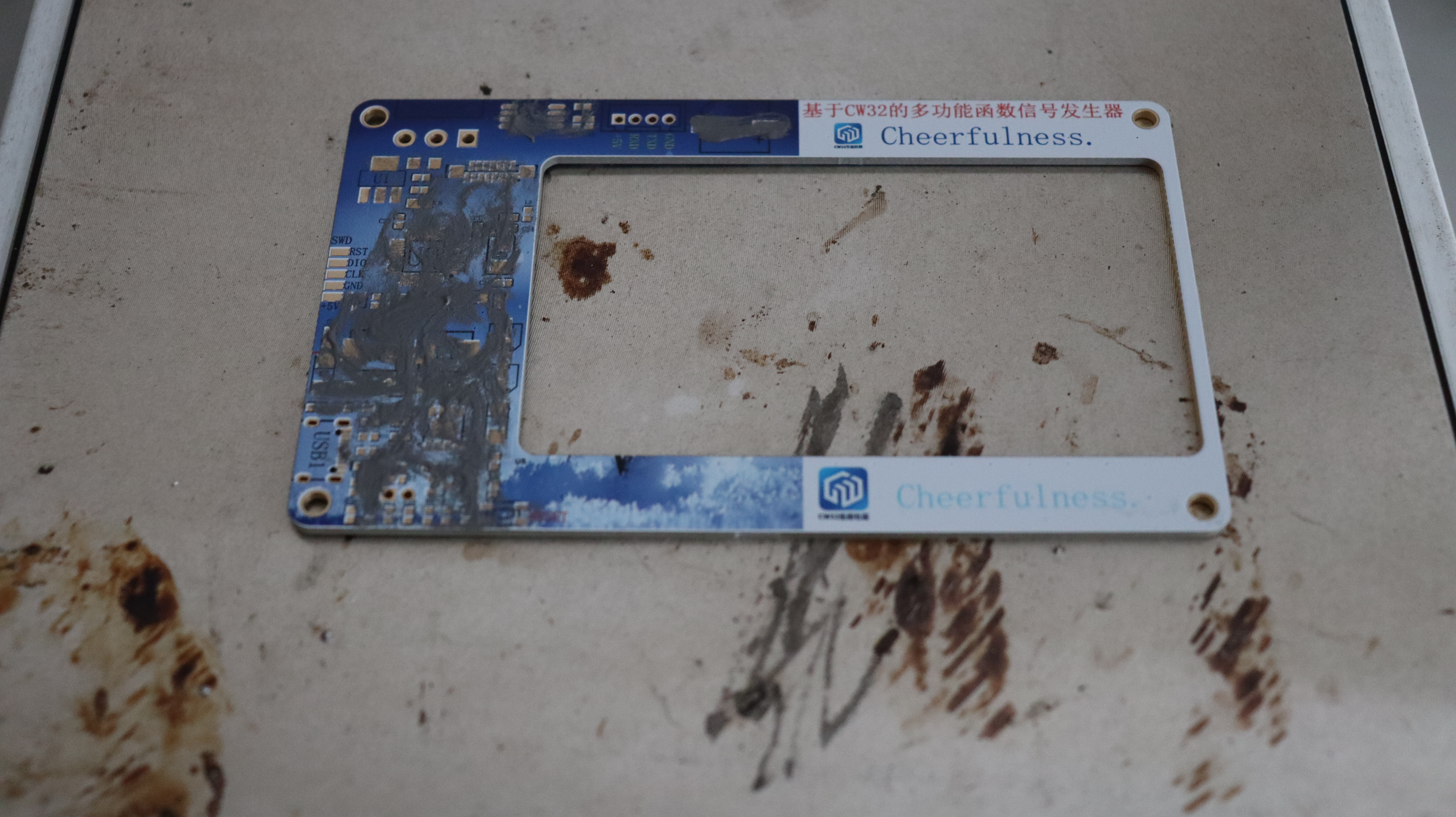
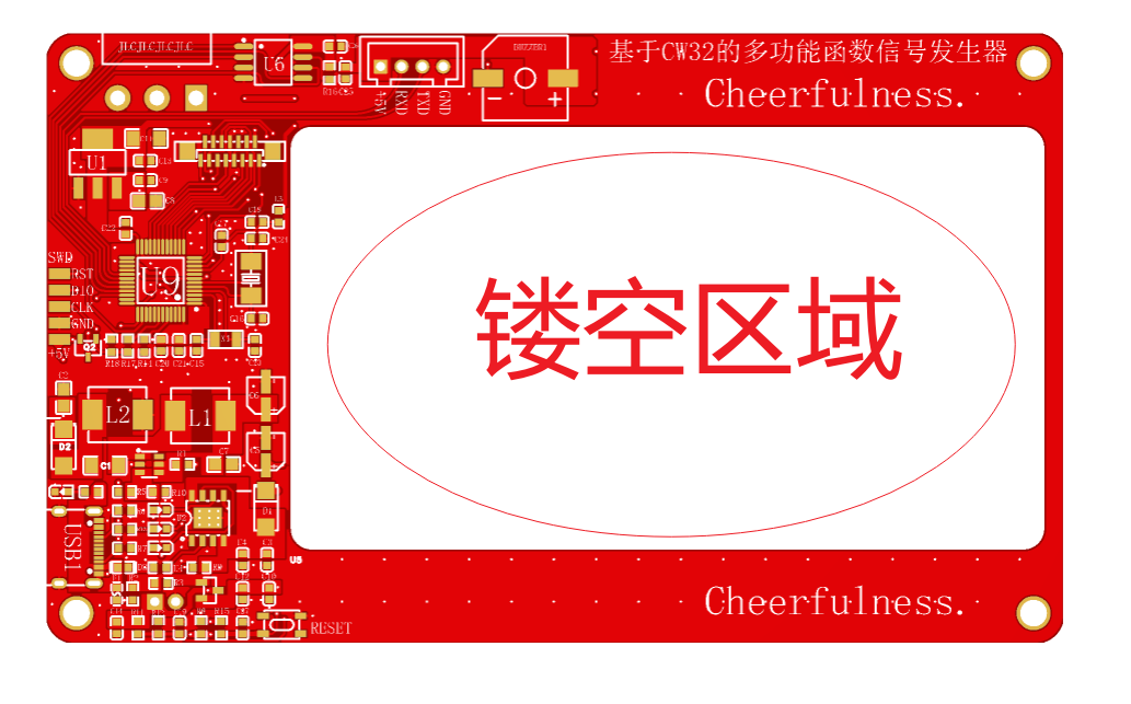
the first circuit board designed in this project was red, using a 1008 package inductor. However, during actual testing, it was found that it couldn't power the 4.3-inch screen. I disassembled it and replaced it with a larger package 6050 22uH inductor, and it worked fine. 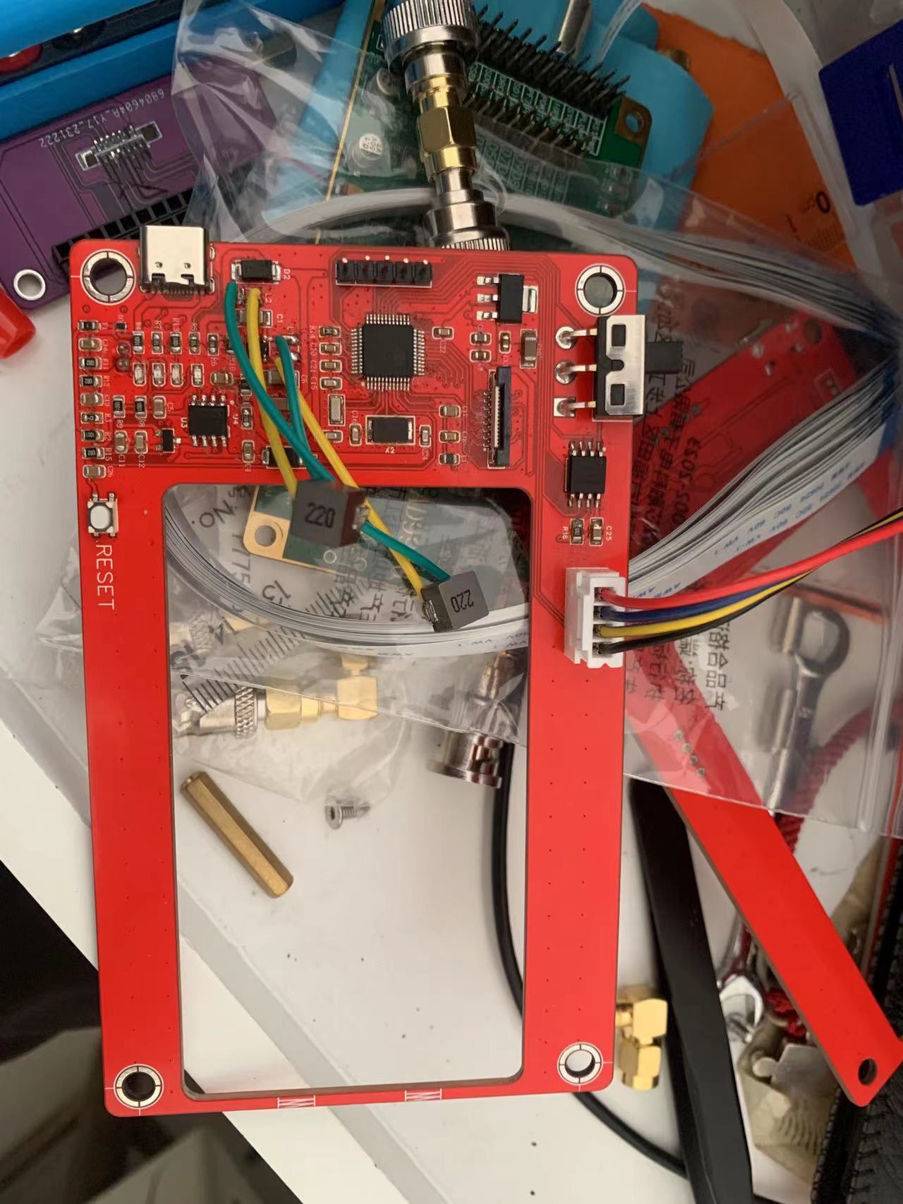 Therefore, in actual circuits, the selection of energy storage components is very important. Both the AD9910 and the 4.3-inch screen require a relatively large current supply, and the integrated buzzer also requires a significant current to drive.


 京公网安备 11010802033920号

 AM2D-1207SZ


