Introducing a simple and highly scalable application solution - a data acquisition instrument developed based on the MM32W series.
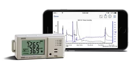
Figure 1 Solution application diagram
In industrial control sites, it is often necessary to collect a large amount of field data in real time, such as voltage, current, temperature, humidity, air pressure, etc. Often these small signals need to be input into professional data acquisition modules for processing, which in turn will collect the collected data. The data is transmitted to the host for processing, and the host transmits control signals to the on-site execution module to perform various operations based on the processing results. At present, data transmission is basically based on wired networks, such as RS485 , CAN , etc. These wired networks generally have disadvantages such as relatively high cost and inconvenient maintenance. Wireless transmission has certain advantages, such as low cost, high reliability, and easy maintenance. This article will introduce the implementation process of a simple Bluetooth data acquisition system based on MM32W series MCU .
Hardware resources are as follows:
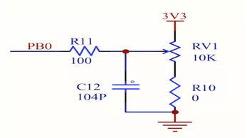
This solution is tested and verified based on the MM32 BLE_Test Board . In order to simply simulate the collection and processing of sensor signals, in terms of hardware principles, this solution directly uses the ADC potentiometer RV1 on the DEMO board to adjust different input signal conditions. The signal is connected to pin PB0 , which can be reused as AD sampling channel CH8 ; use PB1 to connect to the green LED indicator light, which can be used as an indication of Bluetooth connection status , and the low-power wake-up pin selection PA0 is configured as a pull-down input ;The Bluetooth-related function pins are consistent with the solution introduced earlier, so we won’t go into too much detail here.
Software resources are as follows:
Combined with the hardware resources used above, below we focus on the software implementation process and related configuration codes, which mainly involve the configuration of ADC analog channels and corresponding pins, plus the configuration and use of ADC sampling.
The following is the main function initialization configuration and related global variable definitions. It mainly initializes all peripheral resources, Bluetooth broadcast messages and Bluetooth protocol stack, and runs Bluetooth in a blocking manner. The code is as follows:
const unsigned char AdvDat_HRS[]=
{// Define broadcast message
0x02,0x01,0x06,
0x03,0x19,0x41,0x03,
0x07,0x03,0x0D,0x18,0x0A,0x18,0x0F,0x18
};
int main(void)
{
BSP_Init();// Initialize SPI IO and ADC
radio_initBle(TXPWR_0DBM, &ble_mac_addr);// Initialize the Bluetooth chip and Bluetooth protocol stack, and define the transmit power
ble_set_adv_data((unsigned char *)AdvDat_HRS, sizeof(AdvDat_HRS));// Set BLE broadcast data
SysTick_Count = 0;
while(SysTick_Count <= 1500){}; // Wait for at least 5ms after initializing the Bluetooth protocol stack before officially running Bluetooth
Write_Iwdg_ON(IWDG_Prescaler_32, 0x4E2); // Set the IWDG watchdog to prevent the program from running away. The system will restart if the dog is not fed for 1 second .
ble_run(160*2); // Use blocking mode to run Bluetooth protocol, broadcast interval is 200ms
}
Next, we will introduce several functions related to ADC operation:
// When you need to report the real-time ADC conversion value to the APP , call the following function to obtain the average sampling value of the ADC channel.
/****************************************************** *************************************************** *****
** Function information : Get_Adc_Average(uint8_t ADC_Channel_x,uint8_t times)
** Function description : Get the average value of several ADC1 sampling values
** Input parameters : ADC_Channel_x, x is 0~11
** Output parameters : puiADData is the value read by ADC
*************************************************** *************************************************** ****/
u16 Get_Adc_Average(uint8_t ADC_Channel_x,uint8_t times)
{
u32 temp_val=0;
u8t;
u8 delay;
for(t=0;t<times;t++)
{
temp_val+=ADC1_SingleChannel_Get(ADC_Channel_x);
for(delay=0;delay<100;delay++);
}
return temp_val/times;
}
/***************************************************************************************************
**函数信息 :ADC1_SingleChannel_Get()
**功能描述 :获取ADC1转换数据
**输入参数 :ADC_Channel_x , x为0~11
*puiADData ,ADC1实际转换数据
**输出参数 :ucStatus ,0 表示数据获取失败,1 表示成功
***************************************************************************************************/
u16 ADC1_SingleChannel_Get(uint8_t ADC_Channel_x)
{
u16 puiADData;
ADC_SoftwareStartConvCmd(ADC1, ENABLE); // ADCR寄存器的ADST位使能,软件启动转换
while(ADC_GetFlagStatus(ADC1,ADC_FLAG_EOC)==0); //等待ADC转换完成标志位置位
ADC_ClearFlag(ADC1, ADC_FLAG_EOC);//清除ADC转换完成标志位置位
puiADData=ADC1->ADDATA&0xfff;//读取ADC转换值
return puiADData;
}
/********************************************************************************************************
**函数信息 :void ADC1_SingleChannel(uint8_t ADC_Channel_x)
**功能描述 :配置ADC1单次转换模式
**输入参数 :ADC_Channel_x , x为0~11
**输出参数 :无
********************************************************************************************************/
void ADC1_SingleChannel(uint8_t ADC_Channel_x)
{
ADC_InitTypeDef ADC_InitStructure;
RCC_APB2PeriphClockCmd(RCC_APB2Periph_ADC1, ENABLE);
ADC_InitStructure.ADC_PRESCARE = ADC_PCLK2_PRESCARE_16;//初始化ADC分频
ADC_InitStructure.ADC_Mode = ADC_Mode_Single;//初始化ADC工作模式
ADC_InitStructure.ADC_ContinuousConvMode = DISABLE;//禁止连续转换
ADC_InitStructure.ADC_DataAlign = ADC_DataAlign_Right; //初始化ADC转换对齐方式
ADC_InitStructure.ADC_Resolution = ADC_Resolution_12b;//初始化ADC采样精度
ADC_Init(ADC1, &ADC_InitStructure);//初始化ADC
ADC_RegularChannelConfig(ADC1, DISABLE_ALL_CHANNEL , 0, 0); //屏蔽所有ADC通道
ADC_RegularChannelConfig(ADC1, ADC_Channel_x, 0, ADC_SampleTime_13_5Cycles); //使能选中通道
if(ADC_Channel_x == ADC_Channel_11)
{
ADC_VrefintCmd(ENABLE);//如果为通道11,则使能内部参考电压
}
ADC_Cmd(ADC1, ENABLE); //使能ADC1
}
我们在gatt_user_send_notify_data_callback函数中给手机发送数据,该函数属于回调函数,协议栈会在系统允许的时候(异步)回调本函数,该函数可用于蓝牙模块端主动发送数据之用,函数内部不得增加阻塞代码。在本应用中我们在此函数中实现将ADC采集并且转换后的数据传输给手机APP。详细实现代码如下:
// After the Bluetooth connection is successful, the protocol will call this callback function when it is idle.
void gatt_user_send_notify_data_callback(void){
static unsigned char HRMData[3]={0x00,0x00,0x01};// Define the storage area for loading ADC values
static unsigned char SimBatt=100; // Define the storage area for loading ADC percentage value
static u8 Cont=0; // Callback times counter
u16 Val=0;
Cont++; // Every time the function is entered, the callback count counter +1
if (Cont >= 20)
{// ADC data is sent once every 20 times the callback function is entered.
Cont = 0;
Val = Get_Adc_Average(ADC_Channel_3,5); // Get the average of 5 ADC conversions
Val = Val>>3; // 0~511 for HRM data
cur_notifyhandle = 0x12;//ADC data reply handle value
if (Val<0x100)
{
HRMData[0] = 0; //1Byte
HRMData[1] = Val;
sconn_notifydata(HRMData,2);// After converting and processing the ADC data, send it out through Bluetooth
}
else
{
HRMData[0] = 1; //2Byte
HRMData[1] = Val;
HRMData[2] = Val>>8;
sconn_notifydata(HRMData,3);// After converting and processing the ADC data, send it through Bluetooth
}
}
else if (10 == Cont) {// ADC data is sent once every 10 times the callback function is entered
Val = Get_Adc_Average(ADC_Channel_3,5); // Get the average of 5 ADC conversions
Val = Val>>3;
SimBatt = (Val*100)>>9; //0~100
cur_notifyhandle = 0x18;//ADC percentage form data reply handle value
sconn_notifydata(&SimBatt,1);/ After converting and processing the ADC percentage, send it through Bluetooth
}
}
In addition to the above-mentioned key Bluetooth data sending functions, the following briefly introduces some Bluetooth-related characteristic value definitions:
The two characteristic values in this case are defined in const BLE_CHAR AttCharList[] :
{TYPE_CHAR,0x11,ATT_CHAR_PROP_NTF, 0x12,0, 0x37,0x2A, UUID16_FORMAT},//ADC value
{TYPE_CHAR,0x17,ATT_CHAR_PROP_RD|ATT_CHAR_PROP_NTF, 0x18,0,0x19,0x2A,UUID16_FORMAT},// percentage form
Custom characteristic value service declaration is implemented in void att_server_rdByGrType(u8 pdu_type, u8 attOpcode, u16 st_hd, u16 end_hd, u16 att_type) .
The mobile phone operation process is as follows:
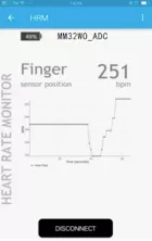
Turn on Bluetooth on your phone and open the App , select HRM to enter, and click the Connect button to start searching for temperature and humidity Bluetooth devices.
Select the Bluetooth device with the corresponding name ( MM32W0_ADC ) and pair it, waiting for the connection to be successful. After the connection is successful, there will be a corresponding prompt, and the name of the button Connect will change to Disconnect .
After the connection is successful, the battery icon on the App interface will display the ADC data information obtained from the potentiometer divider on the DEMO board (relationally converted or in percentage form, not the actual conversion value).
All reference designs on this site are sourced from major semiconductor manufacturers or collected online for learning and research. The copyright belongs to the semiconductor manufacturer or the original author. If you believe that the reference design of this site infringes upon your relevant rights and interests, please send us a rights notice. As a neutral platform service provider, we will take measures to delete the relevant content in accordance with relevant laws after receiving the relevant notice from the rights holder. Please send relevant notifications to email: bbs_service@eeworld.com.cn.
It is your responsibility to test the circuit yourself and determine its suitability for you. EEWorld will not be liable for direct, indirect, special, incidental, consequential or punitive damages arising from any cause or anything connected to any reference design used.
Supported by EEWorld Datasheet
EEWorld
subscription
account

EEWorld
service
account

Automotive
development
community

Robot
development
community

About Us Customer Service Contact Information Datasheet Sitemap LatestNews


Room 1530, 15th Floor, Building B,
No.18 Zhongguancun Street,
Haidian District,
Beijing, Postal Code: 100190
China
Telephone: 008610 8235 0740
 京公网安备 11010802033920号

 MJHS-07R1-48Q-018-6J61


