Original text in CSDN
Project practice-takeaway self-pickup cabinet 1. Project introduction and agreement formulation
Project practice-takeaway self-pickup cabinet 2. Getting started with CubeMX + FreeRTOS
Project practice-takeaway self-pickup cabinet 3. Application of FreeRTOS main API
Project practice-takeaway self-pickup cabinet 4. FreeRTOS stack allocation and debugging skills
Project practice-takeaway self-pickup cabinet 6. Hardware work (schematic diagram, PCB drawing)
Takeaway self-pickup cabinets, similar to express cabinets such as Honeycomb. work process:
Basic functions include communicating with the server, controlling cabinet opening, displaying information, sound prompts, verification code input, etc.
The server and APP are made by others. I make the device side and use the following cabinet.

Solution: MCU + WIFI module + GPRS module + display + keyboard selection: stm32f103rbt6 + esp8266 + sim800 + lcd color screen + matrix keyboard
At first I thought this project was so easyBad streets, at first glance, it is true that this selection is too bad (laughs). If this is an electronic competition problem, it can be solved in a few days, but in the end it took about two months...
The main workflow on the device side is as follows:
The prototype of the protocol part was decided by students who were working on the server. This part directly caused the system to change from streaking to running FreeRTOS.
Frame header + Length + CmdId + DevId + Content + FrameId + Checksum
| Element | describe |
|---|---|
| Frame header | 0x0a 0x0a 0x0a 0x0a |
| Length | The total length of the instruction in bytes, including itself and the checksum, an unsigned short type of two bytes, in the order [low byte, high byte] |
| CmdId | Id of the instruction, an unsigned byte type of one byte |
| DevId | The ID of the target device, a two-byte unsigned short type, in the order [low byte, high byte] |
| Content | The details contained in this instruction |
| FrameId | The unique ID of each frame, a two-byte unsigned short type, in the order [low byte, high byte] |
| Checksum | One byte signed byte type |
The Content of different instructions is different:
After getting started with FreeRTOS, we will focus on the communication part and reorganize the requirements for communication with the server:
The device communicates with the server. Every time the sender sends an instruction, the receiver must return a response frame after receiving it. Only after the sender receives the response frame will it judge that the communication is normal. If the response frame is not received within the specified time , then resend. In addition, it should be noted that the sender cannot block the system operation while waiting for the receiver to return a response frame. That is to say, even if there is currently a frame of data waiting for a response, it will not affect the sending of the next frame of data, and theoretically it should be guaranteed The number of frames waiting for acknowledgment at the same time is unlimited .
Based on the above requirements, it is obvious that the sending of each frame should be treated as a separate task . This task monitors this frame and controls retransmission. As long as the system has enough remaining stacks, it can continuously create new sending tasks, thus ensuring maximum use of hardware resources to ensure "parallel" communication in each frame. It just so happens that FreeRTOS can pass in a parameter when creating a task , and this parameter can pass in the data we want to send. The first task was born: the data sending task:
/**
  * @brief  数据发送任务
  * @note   需要向服务器发送一条指令时,就创建一个发送任务,特点是等待回复和重发时不会阻塞其他任务进行
  * @param  argument:要发送的数据
  * @retval None
  */
void SendData_Task(void const * argument)
{
    //待添加
    for(;;)
    {
        //待添加
    }
}
Let’s think about what to write in the function body:
First of all, data must be sent. Before sending data, there is one thing to consider. Since the argument passed in is a pointer, while this task is in progress, the content pointed to by this pointer is likely to be changed by other tasks, so what is needed first First apply for space to copy the data to be sent. Let’s review the frame format: Frame header + Length + CmdId + DevId + Content + FrameId + Checksum
| Element | describe |
|---|---|
| Frame header | 0x0a 0x0a 0x0a 0x0a |
| Length | The total length of the instruction in bytes, including itself and the checksum, an unsigned short type of two bytes, in the order [low byte, high byte] |
| CmdId | Id of the instruction, an unsigned byte type of one byte |
| DevId | The ID of the target device, a two-byte unsigned short type, in the order [low byte, high byte] |
| Content | The details contained in this instruction |
| FrameId | The unique ID of each frame, a two-byte unsigned short type, in the order [low byte, high byte] |
| Checksum | One byte signed byte type |
我们通过上述的Length获取数据长度,然后用FreeRTOS提供的API: pvPortMalloc 申请内存,这个函数与C语言的malloc的区别是,前者从FreeRTOS的TOTAL_HEAP_SIZE中申请空间,而后者是从系统的堆(heap)中申请空间。 详细的分析看这篇博客: https://www.cnblogs.com/LinTeX9527/p/8007541.html
数据发送任务的前几行代码有着落了:
void SendData_Task(void const * argument)
{
    uint8_t *Data;              //创建指针
    uint16_t Data_Len = 0;      //数据长度
    Data_Len = ((uint16_t*)argument)[0];//获取数据长度
    Data = pvPortMalloc(Data_Len-1);    //申请内存,去掉校验和1字节
    memcpy(Data,(uint8_t*)argument,sizeof(uint8_t)*(Data_Len-1));   //复制数组,去掉校验和
    for(;;)
    {
        //待添加
    }
}当然,如果这里严谨一点的话,你会发现,即便这里进行了数据拷贝,但拷贝也不是一瞬间完成的,所以拷贝的时候,这段数据仍然不是安全的,仍可能被更改,下面就用到FreeRTOS的另一个功能了: 互斥量
正如其名,一个资源在被一个任务访问时,不能再被另一个任务访问,就叫互斥。 通过下面两个函数实现互斥:
osMutexWait(mutex_CopyData_h, osWaitForever);   //等待互斥量被释放
osMutexRelease(mutex_CopyData_h); //释放互斥量这其中mutex_CopyData_h是互斥量的句柄(可以看作是名称),osWaitForever表示一直阻塞等待,直到互斥量被释放。
如何使用呢? 按照上述情形举例,我们要在拷贝数据时用互斥量进行保护,数据发送任务就改进为下面这种形式:
/**
  * @brief  数据发送任务
  * @note   需要向服务器发送一条指令时,就创建一个发送任务,特点是等待回复和重发时不会阻塞其他任务进行
  * @param  argument:要发送的数据
  * @retval None
  */
void SendData_Task(void const * argument)
{
    uint8_t *Data;              //申请内存指针
    uint16_t Data_Len = 0;      //数据长度
    Data_Len = ((uint16_t*)argument)[0];//获取数据长度
    Data = pvPortMalloc(Data_Len-1);    //申请内存,去掉校验和1字节
    osMutexWait(mutex_CopyData_h, osWaitForever);   //等待互斥量被释放
    /*被互斥量保护的区域*/
    memcpy(Data,(uint8_t*)argument,sizeof(uint8_t)*(Data_Len-1));
    /*被互斥量保护的区域*/
    osMutexRelease(mutex_CopyData_h);   //释放互斥量
    for(;;)
    {
        //待添加发送函数
    }
}osMutexWait和osMutexRelease之间,就是我们希望保护的位置。 当然这只完成了一半,同样的,我们需要在存在数据覆盖风险的位置设置互斥量的保护区。
例如下面:传入数据发送任务的参数是名为Data_Buf的数组
osThreadDef(DATA_SEND_TASK_H,SendData_Task, osPriorityHigh,0, 128); //心跳帧重发任务的宏
osThreadCreate(osThread(DATA_SEND_TASK_H),Data_Buf)
那么我需要在修改Data_Buf的位置设置互斥量保护区:
osMutexWait(mutex_CopyData_h, osWaitForever);   //等待互斥量被释放
Data_Buf[0] = 0;
osMutexRelease(mutex_CopyData_h);   //释放互斥量
被互斥量保护的区域,同时只能被一个任务访问,直到这个任务释放互斥量,下一个任务才能访问。 这样,我们就可以保证拷贝数据的时候,数据不会被误修改。
我们继续完善数据发送任务,回到需求分析,数据发送任务除了需要完成数据发送,还需要监听是否收到与此帧数据匹配的应答帧。
如果同时有好几个数据发送任务在等待应答帧,这时候收到了一条应答帧,对于某一个数据发送任务来说,如何判断这条应答帧是发给自己的呢?
上翻查阅数据帧格式的表格,可以看到,每一帧数据有唯一的FrameId,回复帧也有FrameId,它的FrameId与它要回复的数据帧的FrameId相同。
对于某一个数据发送任务来说,它只需要与收到的回复帧的FrameId进行匹配,若与自己的Frame相同,则判断这个回复帧是回复给自己的,如果是回复给自己的,这个数据发送任务就完成了自己的使命,可以把自己删除了。
所以当有多帧数据同时等待回复帧时,需要开设一个缓存区,存放收到的回复帧的FrameId,供数据发送任务查询。
这个缓存区,就交给 消息队列来完成
FreeRTOS对消息队列的处理,我用到了下面几个API:
//查询队列中元素的个数
osMessageWaiting(MsgBox_Frame_Id_Handle);
//获取并删除队列中的一个元素
osMessageGet(MsgBox_Frame_Id_Handle,osWaitForever);
//向队列存放一个元素
osMessagePut(MsgBox_Frame_Id_Handle,evt.value.v,osWaitForever);如何实现查询队列中是否有与自己匹配的FrameId呢?
我的思路是,先通过osMessageWaiting读出当前队列中元素的数量N ,进入循环,每个循环中,使用osMessageGet取出一个元素,由于队列是先进先出,所以这个元素是从队列头部取出的,判断是否匹配,如果匹配,皆大欢喜,这个数据发送任务就解脱了;如果不匹配,再将这个元素用osMessagePut重新加入到队列尾部,这样循环N次,就相当于把队列查询了一遍。
数据发送任务就基本完成了:
/**
  * @brief  数据发送任务
  * @note   需要向服务器发送一条指令时,就创建一个发送任务,特点是等待回复和重发时不会阻塞其他任务进行
  * @param  argument:要发送的数据
  * @retval None
  */
void SendData_Task(void const * argument)
{
    uint8_t *Data;              //申请内存指针
    uint16_t Data_Len = 0;      //数据长度
    Data_Len = ((uint16_t*)argument)[0];//获取数据长度
    uint16_t FrameId = 0;       //帧Id
    uint32_t MsgBox_Data_Num = 0;//队列中有效数据的数量
    osEvent evt;                //存放osMessageGet的返回值
    Data = pvPortMalloc(Data_Len-1);    //申请内存,去掉校验和1字节
    osMutexWait(mutex_CopyData_h, osWaitForever);   //等待互斥量被释放
    /*被互斥量保护的区域*/
    memcpy(Data,(uint8_t*)argument,sizeof(uint8_t)*(Data_Len-1));
    /*被互斥量保护的区域*/
    osMutexRelease(mutex_CopyData_h);   //释放互斥量
    FrameId = (uint16_t)Data[Data_Len-2]<<8|(uint16_t)Data[Data_Len-3]; //装载这一帧数据的FrameId
    for(;;)
    {
        osMutexWait(mutex_id_Resend, osWaitForever);//获取互斥量,防止其他的数据发送任务打断
        MsgBox_Data_Num = osMessageWaiting(MsgBox_Frame_Id_Handle); //获取当前队列数量
        if(MsgBox_Data_Num != 0)        //如果队列非空
        {
            for(i=0;i<MsgBox_Data_Num;i++)
            {
                evt = osMessageGet(MsgBox_Frame_Id_Handle,100); //从队列中取出一个元素
                if(evt.value.v == FrameId)      //如果FrameId匹配
                {
                    /****删除任务****/
                    osMutexRelease(mutex_id_Resend);    //释放令牌
                    vPortFree(Data);                    //释放内存
                    osThreadTerminate (NULL);           //删除本任务
                }
                else        //如果不匹配
                {
                    osMessagePut(MsgBox_Frame_Id_Handle,evt.value.v,500) //存回队列尾
                }
            }
        }
        User_SendData(Data,Data_Len);   //发送数据
        osMutexRelease(mutex_id_Resend);//释放互斥量
        osDelay(5000);  //每5s检测一次
    }
}
除了上面的思路,我这里还使用了一个互斥量,用以保护整个发送过程,因为当有多个数据发送任务都再执行时,队列的取出和放回动作可能会被打断,出现某种极端情况。 例如任务A刚刚从队列中取出一个元素,发现跟自己的FrameId不匹配,但还没来得及放回去,CPU控制权就被任务B抢去了,任务B查询的时候,就少了这个任务A取走的元素,造成误判。 另外,发送数据是通过串口的,执行时间也比较长,如果发送时被打断,可能造成不可预估的后果,所以使用互斥量进行保护是十分有必要的。
在整个项目中,主要用到的就是上面几个API,数据发送任务,也是仅有的稍显复杂的任务,另外还有一些调试用的API,下一节更新。
根据功能划分了下面几个任务
这里简单列两个 人机交互任务:
/**
  * @brief  人机交互任务
  * @note   包括按键扫描、LCD显示、蜂鸣器鸣叫
  * @param  argument:任务参数(未用到)
  * @retval None
  */
void Interactive_Task(void const * argument)
{
    for(;;)
    {
        /**矩阵键盘扫描**/
        /**键值处理**/
        /**LCD显示**/
        /**蜂鸣器扫描**/
        osDelay(20);
    }
}
无线模块管理任务:
/**
  * @brief  无线模块管理任务
  * @note   检测服务器是否离线,若离线则重新初始化无线模块
  * @param  argument:任务参数(未用到)
  * @retval None
  */
void WirelessCTR_Task(void const * argument)
{
    osDelay(1000);      //等待ESP8266上电
    for(;;)
    {
        if(server_sta == SERVER_OFF_LINE)   //服务器离线
        {
//          osThreadSetPriority(NULL,osPriorityHigh);   //调高优先级,防止打断
            esp8266_init();     //初始化esp8266
//          osThreadSetPriority(NULL,osPriorityNormal); //调低优先级
        }
        osDelay(20);
    }
}
 配置TCP透传,用到的AT指令如下:
| AT指令 | 功能 |
|---|---|
| AT | 测试硬件是否正常 |
| ATE0 | 关闭回显 |
| AT+CWMODE=1 | 设置为客户端 |
| AT+CIPSTATUS | 判断状态:返回2表示已正常连接WIFI;返回3表示已正常连接服务器 |
| AT+CWJAP="MyWIFI","123456" | Connect to WIFI |
| AT+CWAUTOCONN=1 | Set to automatically connect to WIFI mode |
| AT+CIPSTART="TCP","192.111.1.1",8888 | connect to the server |
| AT+CIPMODE=1 | Set to transparent transmission mode |
| AT+CIPSEND | Start transparent transmission |
| +++ | Turn off passthrough |
Initialization flow chart:
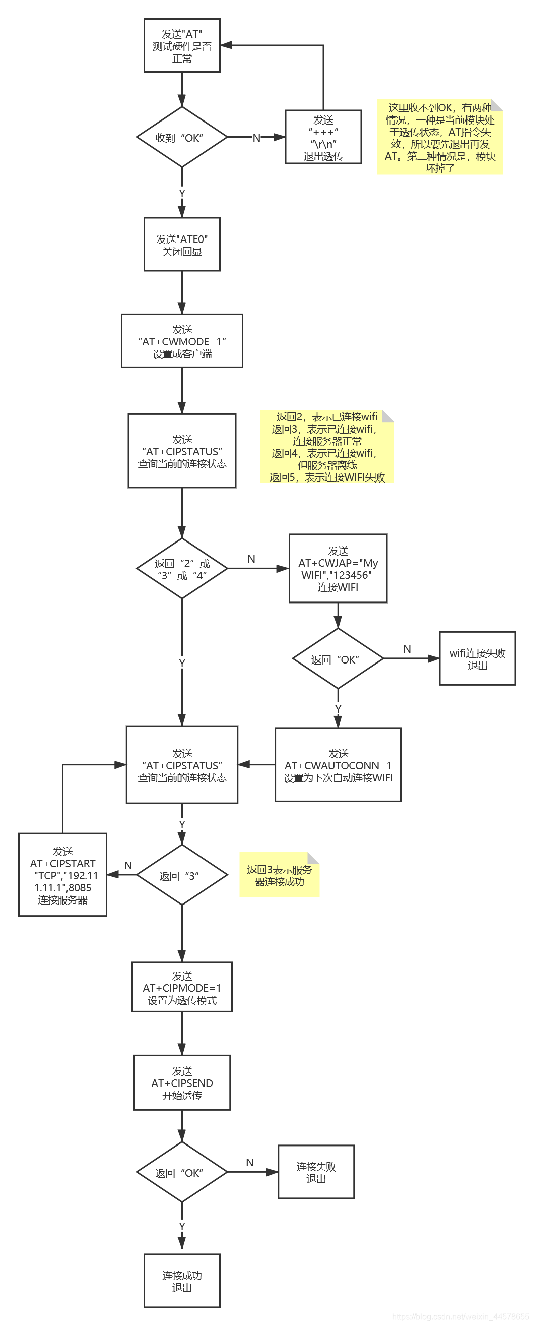
The basic idea is to open an array, store the received return value in the array, wait for a period of time after sending the command, read the array, and use the **strstr()** function to determine whether there is an expected return value in the array. , clear the array after the search is completed. Take the AT instruction as an example:
usart3_tx_dma_enable((uint8_t*)"AT",2); //发送AT指令
osDelay(50);    //等待50ms
if(strstr(mes_buf,"OK")!=NULL)  //找到对应字符串
    res = 1;            //返回1,否则返回0
else
    res = 0;
clear_mes_buf();    //清空缓冲
return res;Send "+++" without adding it, but this will cause the next AT command to be invalid. Therefore, after sending +++, you have to send another one before the subsequent AT command can take effect.
//关闭透传
void close_tran()
{
    usart3_tx_dma_enable((uint8_t*)"+++",3);    //发送+++
    osDelay(500);   //延时500ms
    usart3_tx_dma_enable((uint8_t*)"
",2);   //实际测试时,发完+++以后,还需要一个指令(带
)激活模块
    osDelay(100);   //延时100ms
}Under normal circumstances, if the server suddenly goes offline during the transparent transmission process, a closed message will be returned. However, since it has been in transparent transmission mode before, it is difficult for the microcontroller to capture this closed message, so other means need to be used to determine whether the server is abnormally offline.
In the protocol of this project, there is a heartbeat and reply frame mechanism, which can determine whether the server is online based on whether the sent heartbeat is replied to. If abnormal offline is detected, re-initialize the ESP8266, and then further determine whether the WIFI is abnormal and the server is abnormal, and locate the problem.
ESP8266 and SIM800 power supply selection circuit:

Here, an NMOS and a PMOS are used to implement module switching, and the test results are normal.
Electromagnetic lock drive circuit

I use NMOS, and the gate resistor can be smaller. I actually use 470R. You can even short-circuit the gate resistor here. R39 is for gate pull-down to prevent the output from being unstable when the IO port is floating. D13 is a freewheeling diode, and the electromagnetic lock is an inductive component to prevent the MOS from breakdown instantly when it is turned off.
The smallest system part of a microcontroller

There is an anti-reverse connection circuit here, mainly because the SWD interface is easy to be plugged in reversely and burn the microcontroller. Q16 is an NMOS, used to prevent reverse connection. The MOS will automatically shut down after being plugged in reversely. R12 is a 0 ohm resistor, so I don’t want to use it. Anti-reverse connection function, R12 can be soldered for short circuit.
USB to TTL part

This fuse has saved me several times, don’t save it! ! ! A 6V 700mA resettable fuse is used.
A little bit of PCB experience, please don’t slander me,
To be honest, this kind of board can be used for any drawing...
The power pin of the chip should be decoupled, and the decoupling capacitor should be close to the pin.


Keep the traces of the crystal oscillator as short as possible, and do not run power lines around the crystal oscillator.

Try not to pass USB signal lines through holes and run them in parallel

Do not lay copper underneath the antenna:

If the layout is very compact, drill more vias in a targeted manner.

1.8-inch TFT screen, SIM800L, ESP8266:

4x4 membrane matrix keyboard:

welding:


I don’t have an air gun...don’t imitate me

Washing plate:

After receiving the picture:

Test video link: Takeaway self-pickup cabinet test video

All reference designs on this site are sourced from major semiconductor manufacturers or collected online for learning and research. The copyright belongs to the semiconductor manufacturer or the original author. If you believe that the reference design of this site infringes upon your relevant rights and interests, please send us a rights notice. As a neutral platform service provider, we will take measures to delete the relevant content in accordance with relevant laws after receiving the relevant notice from the rights holder. Please send relevant notifications to email: bbs_service@eeworld.com.cn.
It is your responsibility to test the circuit yourself and determine its suitability for you. EEWorld will not be liable for direct, indirect, special, incidental, consequential or punitive damages arising from any cause or anything connected to any reference design used.
Supported by EEWorld Datasheet
EEWorld
subscription
account

EEWorld
service
account

Automotive
development
community

Robot
development
community

About Us Customer Service Contact Information Datasheet Sitemap LatestNews


Room 1530, 15th Floor, Building B,
No.18 Zhongguancun Street,
Haidian District,
Beijing, Postal Code: 100190
China
Telephone: 008610 8235 0740
 京公网安备 11010802033920号

 1318027-9


