1. Name of contestant: Mark
2. Name of the entry: Micro Body Measurement Instrument
3. Materials to be used from LiChuang Mall: ESP8266, STM32, PL2303, LCD12864, LM1117, etc.
4. Materials not from LiChuang Mall or other supplements to be used: small components such as resistors and capacitors
5. Name of EDA tool software to be used (required): LiChuang EDA / EasyEDA
6. Original link: http://club.szlcsc.com/article/details_16043_1.html
7. Original project link: https://oshwhub.com/markone/hehe1
. Introduction of the project
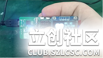
With the improvement of the quality of life and the acceleration of the pace of life, people need to pay more attention to their health. This project aims to design a body parameter testing system based on cloud platform + APP + device side, using pulse sensor, infrared sensor, weak signal detection circuit, etc. to realize the collection of human body parameters, and upload the data to the cloud storage through wireless network or other means, and provide a web-side interactive interface to build a human body parameter management platform for users.


2. System architecture diagram
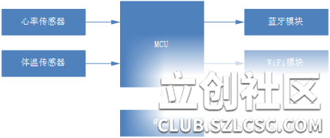
The hardware part of the system consists of MCU, heart rate sensor, temperature sensor, power supply, Bluetooth module, and WiFi module. The software part includes stm32 program design based on C language, upper computer software design, server-side web page and background program design, and APP software design. The hardware architecture and software architecture are shown in the following figures respectively.


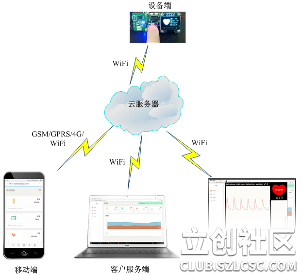
When the system is working, the original AD signals of heart rate and body temperature are collected by heart rate sensor and temperature sensor respectively, and the heart rate and temperature values are calculated by corresponding algorithms, and uploaded to the cloud server through WiFi. The cloud server processes, stores and analyzes the transmitted data, and also issues warnings and prompts through data analysis. Users only need to log in to the corresponding webpage or mobile phone APP to view the real-time and historical data of themselves or their families. In addition, this system also provides a positioning function, and users can view the location of the measurement terminal on the map.

III. Description of the hardware part

1. MCU system circuit
This system uses STM32103C8T6, which is the main control chip. On the one hand, it collects sensor data, and on the other hand, it processes the data through algorithms and forwards it to the cloud server. Therefore, two ADC interfaces are connected to the sensor during circuit design. For the STM32 system, its necessary components also include the startup mode selection circuit, crystal oscillator reset circuit, etc. During the design, I also added indicator lights and buttons as backup. The STM32 system circuit is shown in Figure 4. The power supply voltage of STM32 and the voltage of the heart rate and temperature sensors are all 3.3V, so if 5V voltage is used for power supply, voltage conversion is also required. This system uses LDO regulator LM1117 to convert 5V to 3.3V. For the power supply and switch, the system uses the MICO USB interface for power supply and program downloading. The circuit of this part is shown in the figure.


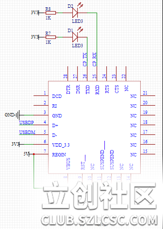
2. USB to serial port circuit
Using USB as the system program download interface, its level needs to be converted to communicate with the serial port of STM32. This system uses CP2102 as the conversion chip. CP2102 has high integration, built-in USB2.0 full-speed function controller, USB transceiver, crystal oscillator, EEPROM and asynchronous serial data bus (UART), supports full-function modem signals, and does not require any external USB devices. The working principle of CP2102 is similar to that of other USB-UART conversion circuits. The driver program virtualizes the USB port of the PC into a COM port to achieve the purpose of expansion. The circuit design diagram of this part is shown in the figure.

3. WiFi module
The WiFi module uses the ESP8266 module. When using this module, its external circuit needs to be designed, including the power supply circuit, reset circuit, mode selection circuit and other parts. The designed circuit diagram is shown in the figure.


IV. Bill of Materials (BOM List):


V. Description of the Software Part
1. Main chip program design
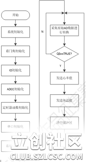
STM32 program design is based on RT-Thread line development. In addition to system initialization, in the main program, the following functions are completed:
1) Collect the AD data of the sensor through the internal AD interface;
2) Process the data through the algorithm;
3) Pack the processed data and provide the WiFi module to send it to the server;
4) Feed the dog. According to the above 4 functions, the program workflow diagram is shown in the figure.

2. Heart rate acquisition algorithm
The goal of the heart rate acquisition algorithm is to find the continuous moments of the instantaneous heartbeat and measure the time interval (IBI) between the two. We are able to do this by following the predictable shape and pattern of the PPG waveform. When the heart pumps blood into the human body, each beat will have a pulse wave (a bit like a shock wave) along all the arteries to the end of the capillary tissue where the pulse sensor is attached. The actual blood circulation is much slower than the pulse wave propagation. Start tracking events from point T on the PPG shown in the figure below. When the pulse wave passes under the sensor, the signal value rises rapidly, and then the signal falls back to the normal point. Sometimes, the bi-directional cut (downward spike) is more obvious than others, but usually the signal settles to background noise before the next pulse wave washes out. Since the waves are repetitive and predictable, you can choose almost any identifiable feature as a reference point, such as a peak, and calculate the heart rate by the time between each peak. However, this may read incorrectly from the bi-directional cut and may also be inaccurate for baseline noise. Ideally, finding the moment when the heart beats requires accurate BPM calculation, heart rate variability (HRV) research, and pulse transit time (PTT) measurement.


By using timer interrupts, our beat finding algorithm runs in the background and automatically updates variable values. The overall algorithm flow chart is shown in Figure

3. Server software and web design
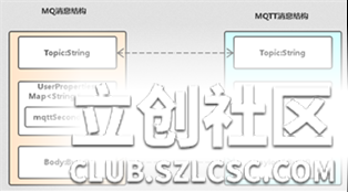
The server side uses the cloud server provided by Alibaba Cloud, and its data transmission protocol is the MQTT protocol. The measurement acquisition end is the device end of MQTT, and the cloud server is the server end of MQTT. The received data is stored in SQL and displayed through the web page. The MQTT protocol data transmission process is shown in the figure.

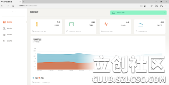
The designed main data interface is shown in Figure

4. APP software design
After the mobile terminal APP is opened for the first time, manual network configuration is performed. When the specified WIFI signal is searched, it is connected, and then the TCP port is monitored, the received data packets are parsed, and then the data is displayed on the screen. The designed APP is shown in the figure below.

5. Upper computer software design
The upper computer software is designed based on JAVA. It receives the data packets transmitted by the measurement terminal through the port and parses them. The real-time status of the heart rate is displayed graphically. Its working interface is shown in the figure.

6. Introduction to RT-Thread transplantation
This section briefly introduces the use of SPI and serial port communications involved in the use of OLED and WIFI modules in this system in RTT, and introduces the function calling process, the use of key functions, and the calling of device drivers.
6.1 OLED
OLED communicates with the chip via the SPI protocol. The device driver usage process is as follows:
(1) Define the device object and call rt_spi_bus_attach_device() to mount the device to the SPI bus.
This function is used to mount an SPI device to the specified SPI bus, register the SPI device with the kernel, and save user_data to the SPI device device.
Parameter
Description
device
SPI device handle
name
SPI device name
bus_name
SPI bus name
user_data
user data pointer
a. First, you need to define the SPI device object device
b. The SPI bus naming principle is spix, and the SPI device naming principle is spixy. The spi10 of this project means mounting on the spi1 device.
c. The SPI bus name can be viewed by entering the list_device command in the msh shell to determine the SPI bus to which the SPI device is to be mounted.
d. user_data is generally the CS pin pointer of the SPI device. When transmitting data, the SPI controller will operate this pin for chip selection.
The source code of rt_hw_ssd1306_config() in the underlying driver drv_ssd1306.c of this project to mount the ssd1306 device to the SPI bus is as follows:
static int rt_hw_ssd1306_config(void)
{
rt_err_t res;
/* oled use PC8 as CS */
spi_cs.pin = CS_PIN;
rt_pin_mode(spi_cs.pin, PIN_MODE_OUTPUT); /* Set the chip select pin mode to output*/
res=rt_spi_bus_attach_device(&spi_dev_ssd1306,SPI_SSD1306_DEVICE_NAME, SPI_BUS_NAME,(void*)&spi_cs);
if (res != RT_EOK)
{
OLED_TRACE("rt_spi_bus_attach_device!
");
return res;
}
}
(2) Call rt_spi_configure() to configure the SPI bus mode.
After mounting the SPI device to the SPI bus, in order to meet the clock, data width and other requirements of different devices, it is usually necessary to configure the SPI mode and frequency parameters. The mode of the SPI slave device determines the mode of the master device, so the mode of the SPI master device must be the same as that of the slave device so that the two can communicate normally.
rt_err_t rt_spi_configure(struct rt_spi_device *device, struct rt_spi_configuration *cfg)
Parameter
descriptiondevice SPI device
handlecfg SPI transmission configuration parameter pointerThis function will save the mode parameters pointed to by cfg to device, and this configuration information will be used when device calls the data transmission function. After mounting the SPI device to the SPI bus, this function must be used to configure the transmission parameters of the SPI device. The source code of rt_hw_ssd1306_config() in the underlying driver drv_ssd1306.c of this project to configure SPI transmission parameters is as follows: static int rt_hw_ssd1306_config(void) { /* config spi */ { struct rt_spi_configuration cfg; cfg.data_width = 8; cfg.mode = RT_SPI_MASTER | RT_SPI_MODE_0 | RT_SPI_MSB; cfg.max_hz = 20 * 1000 *1000; /* 20M,SPI max 42MHz,ssd1306 4-wire spi */ rt_spi_configure(&spi_dev_ssd1306, &cfg); }} (3) Use rt_spi_transfer() and other related data transmission interfaces to transmit data. After the SPI device is mounted on the SPI bus and the relevant SPI transmission parameters are configured, a series of SPI device driver data transmission functions provided by RT-Thread can be called. This function can transmit a series of messages, and the user can flexibly set the values of each parameter of the message structure, so as to conveniently control the data transmission method. (4) To display images and text on the OLED through the device driver call, you first need to determine the starting address of the row and column of the information on the OLED, call ssd1306_write_cmd() to send instructions to SSD1306, and call ssd1306_write_data() to send data to SSD1306. The source code is as follows: void set_column_address(rt_uint8_t start_address, rt_uint8_t end_address){ ssd1306_write_cmd(0x15); // Set Column Address ssd1306_write_data(start_address); // Default => 0x00 (Start Address) ssd1306_write_data(end_address); // Default => 0x7F (End Address) }
void set_row_address(rt_uint8_t start_address, rt_uint8_t end_address)
{ ssd1306_write_cmd(0x75); // Set Row Address
ssd1306_write_data(start_address); // Default => 0x00 (Start Address)
ssd1306_write_data(end_address); // Default => 0x7F (End Address)
}
6.2 Serial
Port The serial port is used to communicate with the WIFI module ESP8266. During the use of the serial port, the following functions are mainly used for initialization:
static void RCC_Configuration(void);static void GPIO_Configuration(void);static void NVIC_Configuration(struct stm32_uart *uart);void rt_hw_usart_init();
(1) In void In rt_hw_usart_init();, the baud rate, serial port number, word length, etc. are set.
The actual path calling process is as follows.
startup.c main() ---> startup.c rtthread_startup() ---> board.c rt_hw_board_init() ---> usart.c rt_hw_usart_init()
(2) In order to include the device in the IO device layer of RTT, a data structure called rt_device needs to be created for this device. This data structure is defined in rtdef.h. Some functions are needed to operate logical devices. These functions are provided in the rt-thread/src/device.c file. They are:
rt_err_t rt_device_register(rt_device_t dev, const char *name, rt_uint16_t flags)
Add the rt_device data structure to the device layer of RTT. This process is called "registration". The device management layer of RTT will create a unique device_id for this data structure.
rt_err_t rt_device_unregister(rt_device_t dev)
is the opposite of registration, which is to cancel the registration and remove a device from the device driver layer of RTT.
rt_device_t rt_device_find(const char *name)
finds a device according to the string name of the device.
rt_err_t rt_device_init(rt_device_t dev)
initializes the device by calling the init function in the rt_device data structure.
rt_err_t rt_device_init_all(void)
initializes all registered devices in the RTT device management layer
rt_err_t rt_device_open(rt_device_t dev, rt_uint16_t oflag)
opens the device by calling the open function in the rt_device data structure.
rt_err_t rt_device_close(rt_device_t dev)
closes the device by calling the close function in the rt_device data structure.
rt_size_t rt_device_read(rt_device_t dev, rt_off_t pos, void *buffer, rt_size_t size)
reads data from the device by calling the read function in the rt_device data structure.
rt_size_t rt_device_write(rt_device_t dev, rt_off_t pos, const void *buffer, rt_size_t size)
writes data to the device by calling the write function in the rt_device data structure (for example, the device is flash, SD card, nand or nor flash, etc.).
(3) The writing process of open, read and other functions is as follows.
Ⅰ..init function completes the initialization of the device data structure. There are a large number of predefined macros in the RTT device driver, which are defined in rtdef.h.
Ⅱ.open
Because the usart device has been initialized in usart.c, the serial port will start working after the USART_Cmd statement is passed in init. Therefore, the open function can be set to empty
, and the close and colse can be set to empty in between.
III.read
static rt_size_t rt_serial_read (rt_device_t dev, rt_off_t pos, void* buffer, rt_size_t size)
pos indicates the read and write position, and buffer is the buffer used to store the read data. Size is the number of bytes. For serial stream devices such as USART, pos is meaningless, so pos here is meaningless. The user_data field of the rt_device data structure dev stores a (struct stm32_serial_device*) type pointer.
IV.write
writes data to the serial port, that is, sends data.
/* polling mode */
if (dev->flag & RT_DEVICE_FLAG_STREAM)
{
/* stream mode */
while (size)
{
if (*ptr == '
')
{
while (!(uart->uart_device->SR & USART_FLAG_TXE));
uart->uart_device->DR = '
';
/* interrupt mode Tx, does not support */
RT_ASSERT(0);
} while (!(uart- >uart_device->SR & USART_FLAG_TXE));
uart->uart_device->DR = (*ptr & 0x1FF); ++ptr; --size;
}
}
else
{
/* write data directly */
while (size)
{
while (!(uart->uart_device->SR & USART_FLAG_TXE));
uart->uart_device->DR = (*ptr & 0x1FF); ++ptr; --size;
}
}
V. Register USART’s rt_device structure
rt_err_t rt_hw_serial_register( rt_device_t device, const char* name, rt_uint32_t flag, struct stm32_serial_device *serial)
{
RT_ASSERT(device != RT_NULL); if ((flag & RT_DEVICE_FLAG_DMA_RX) ||
(flag & RT_DEVICE_FLAG_INT_TX))
{
RT_ASSERT(0);
} device->type = RT_Device_Class_Char;
device->rx_indicate = RT_NULL;
device->tx_complete = RT_NULL;
device->init = rt_serial_init;
device->open = rt_serial_open;
device->close = rt_serial_close;
device->read = rt_serial_read;
device->write = rt_serial_write;
device->control = rt_serial_control;
device->user_data = serial; /* register a character device */
return rt_device_register(device, name, RT_DEVICE_FLAG_RDWR | flag);
}
VI. Work Demonstration
Tencent Video: http://url.cn/5LXX7JF
VII. Conclusion
The design of this work realizes the functions of real-time measurement, remote viewing, cloud storage, analysis prompts and other functions of human body parameters. It is suitable for It can be used in various scenarios as a home medical assistant, personal medical equipment, etc. Compared with traditional equipment, it is low-cost and easy to carry. The cloud data storage function is convenient and fast, and can perform long-term data monitoring and health data analysis. The system is highly compatible. For other smart devices, they can quickly access cloud services. For measurement terminals, other vital sign measurement devices can be added as auxiliary references. At the same time, the system has a lot of room for improvement and upgrading, such as adding lithium batteries. And its charging and discharging circuit realizes its own power supply system. I believe that more deficiencies will be found in future use, and I will continue to improve it!
For more project details, please see the link: http://club.szlcsc.com/article/details_16043_1. htmlThis
project belongs to the LiChuang community "MarkOne"


 京公网安备 11010802033920号

 JPAD10


