This work is licensed under a Creative Commons Attribution-ShareAlike 3.0 Unported License. ( http://creativecommons.org/licenses/by-sa/3.0/ )
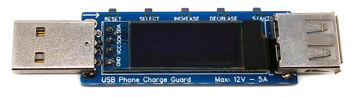
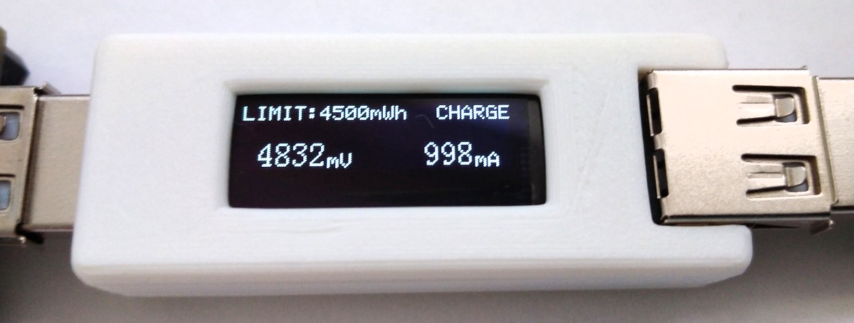
ATtiny45/85 USB Phone Charge Guard controls and monitors charging of phones and other devices. Voltage, current, power and energy are continuously measured via the INA219 and compared with user limit values. When user-selected conditions are reached, it cuts off power through the MOSFET. This controls the charge state of your phone's lithium-ion battery, extending its lifespan. User settings are stored in EEPROM.
Author: Stefan Wagner
Original project link: https://oshwlab.com/wagiminator/attiny85-phone-charge-guard
Project video (YouTube): https://youtu.be/9DHBoqHImcM
Firmware (Github): https://github.com/wagiminator/ATtiny85-PhoneChargeGuard
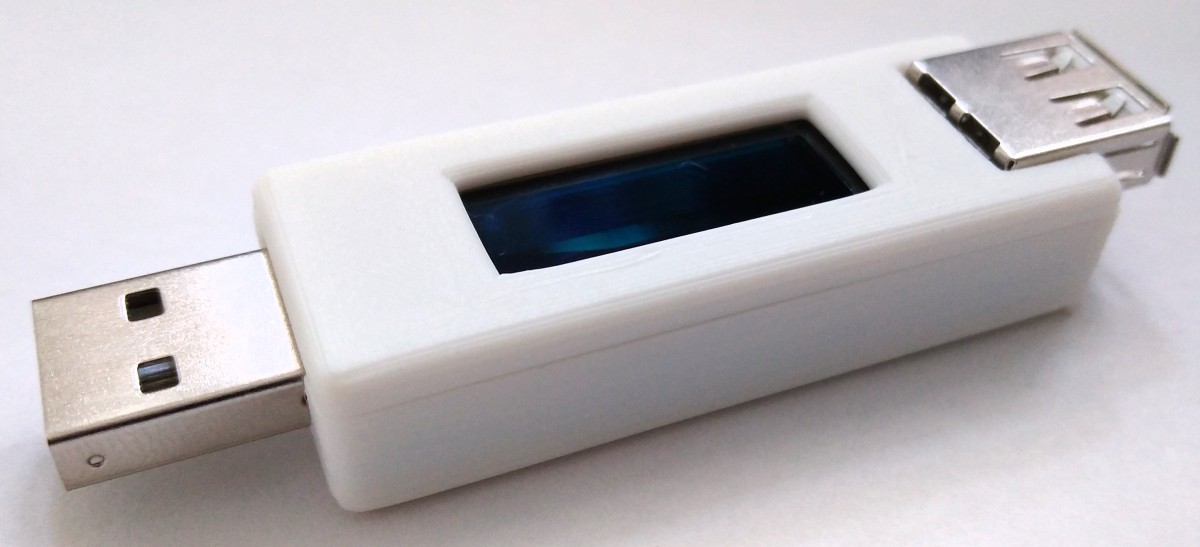
The device comes with a USB-A plug for input and a USB-A socket for output so that it can be plugged in between a power source and your phone (or other consumer). D+ and D- are passed so that the phone can negotiate the charging protocol.
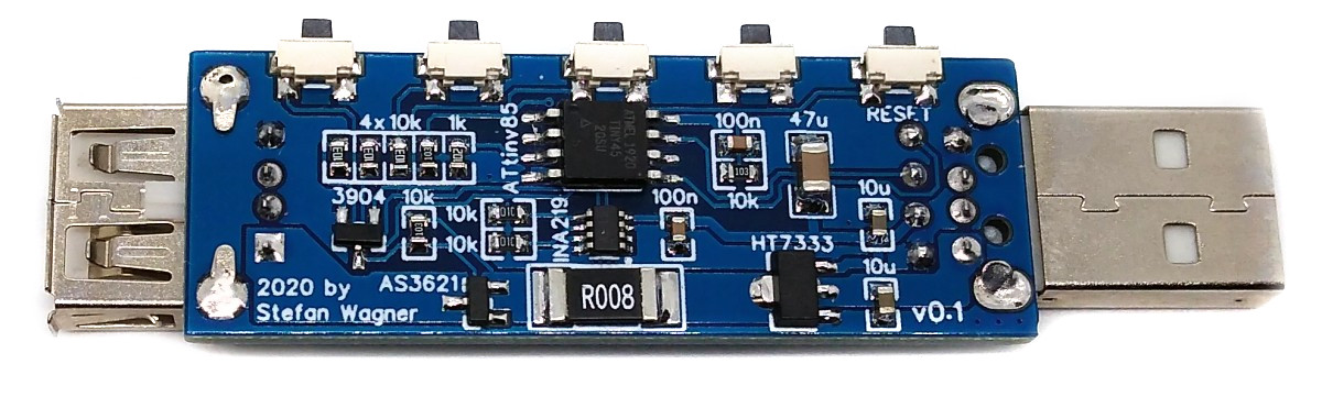
An INA219 is used to measure voltage and current. The INA219 is a current shunt and power monitor with an I²C compatible interface. The device monitors shunt voltage drop and bus supply voltage with programmable transition times and filtering. Programmable calibration values combined with internal multipliers enable direct reading of current in amperes. The 8 milliohm shunt resistor was chosen to have very little effect on the circuit while allowing measurements to be made with 1 milliamp resolution. For accurate measurements, choose a shunt resistor with low tolerance (1% or better)
The device supplies 3.3V via the HT7333 LDO regulator, which draws input voltages up to 12V from the USB bus power.
The connection between the power supply and the phone is turned on and off via the AS3621 P-channel MOSFET. Despite its small size, it can continuously switch to 30V and 6A. Its internal on-resistance is only about 20 milliohms.
The user interface uses five buttons and a 128x64 pixel OLED display. An ATtiny45/85 microcontroller handles the user interface, the power connection of the measured values and the control of the calculation and display.
The INA219 continuously measures current and voltage and transmits the values to the ATtiny via I²C. From this, ATtiny calculates other values and displays them on the OLED screen. It controls the connection between the power supply and the phone through MOSFETs according to the settings selected by the user. User settings are saved in EEPROM and will be loaded automatically the next time you use it.
The I²C protocol implementation is based on a crude bitbanging approach. It is designed specifically for the limited resources of the ATtiny10 and ATtiny13, but it will also work with some other AVRs (including the ATtiny45/85). The OLED functionality is for the SSD1306 OLED module, but can be easily modified for use with other modules. To save resources, only the basic functionality required by this application has been implemented. For more information on how the I²C OLED implementation works, visit TinyOLEDdemo .
The ATtiny's internal oscillator is used to determine energy and capacity. When factory calibrated, the internal oscillator is accurate to +/-10%. This can be improved to +/-2% or better with manual calibration. Calibration values determined in this way can be set in the source code.
Since there is no ICSP header on the board, you must program the ATtiny before soldering using the SOP adapter or after soldering using the EEPROM programming clip. The AVR programming adapter can help in this regard.
- Chip : ATtiny45 or 85 (depending on your chip)
- Clock : 8 MHz (internal)
- Millis/Micros : Disabled
- BODLevel : BOD enabled (2.7V)
- Leave the rest at default settings
Connect your programmer to your PC and ATtiny.
Go to Tools->Programmer and select your ISP programmer (e.g. USBasp).
Go to Tools -> Burn Bootloader to burn the fuse.
Open the PhonChargeGuard sketch and click Upload .
- avrdude -c usbasp -p t85 -U lfuse:w:0xe2:m -U hfuse:w:0xd5:m -U efuse:w:0xff:m -U flash:w:phonechargeguard.hex
Make sure you have the avr-gcc toolchain and avrdude installed. Connect your programmer to your PC and ATtiny. If you are not using ATtiny85, open the makefile and change the chip, if you are not using usbasp, change the programmer. Open a terminal. Navigate to the folder containing the makefile and Arduino sketch. Run "make install" to compile, burn fuses and upload firmware.
| button | Function |
|---|---|
| RESET | reset all values |
| SELECT | Select restriction type in pause mode/change display parameters in charging mode |
| INCREASE | increase limit value |
| DECREASE | Lower limit value |
| START | Start/pause charging |
| Restriction type | Function |
|---|---|
| mAh | Stop charging when the battery reaches the selected value |
| mWh | Stop charging when the supplied energy reaches the selected value |
| mA | Stops charging when the current falls below a selected value (this is usually related to the battery's state of charge) |
| min | Stop charging after selected time in minutes |
| scope | maximum value |
|---|---|
| Voltage | 3V-12V |
| current | 5AMAX |
| Voltage measurement rate | 4mV |
| Current measurement rate | 1mA |

All reference designs on this site are sourced from major semiconductor manufacturers or collected online for learning and research. The copyright belongs to the semiconductor manufacturer or the original author. If you believe that the reference design of this site infringes upon your relevant rights and interests, please send us a rights notice. As a neutral platform service provider, we will take measures to delete the relevant content in accordance with relevant laws after receiving the relevant notice from the rights holder. Please send relevant notifications to email: bbs_service@eeworld.com.cn.
It is your responsibility to test the circuit yourself and determine its suitability for you. EEWorld will not be liable for direct, indirect, special, incidental, consequential or punitive damages arising from any cause or anything connected to any reference design used.
Supported by EEWorld Datasheet
EEWorld
subscription
account

EEWorld
service
account

Automotive
development
community

Robot
development
community

About Us Customer Service Contact Information Datasheet Sitemap LatestNews


Room 1530, 15th Floor, Building B,
No.18 Zhongguancun Street,
Haidian District,
Beijing, Postal Code: 100190
China
Telephone: 008610 8235 0740
 京公网安备 11010802033920号

 CS9236


