The Internet of Things is widely used, and the current smart home system is a typical application of the Internet of Things.
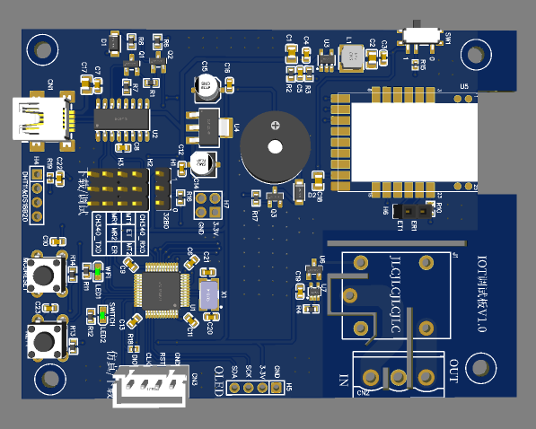
The IoT node based on EMW3080 is a smart home node with EMW3080 module and STM32F103C8T6 as the control core. In this design, EMW3080 is responsible for connecting to the external network, and STM32 is mainly responsible for processing the hardware layer. Now it is the V1 version, which has only one device, which can control the socket on and off, detect the ambient temperature and humidity, and connect to Tmall Genie. With enough time and energy, I will perfect this design in my spare time and build a smart home system, and consider open source it to Lichuang.
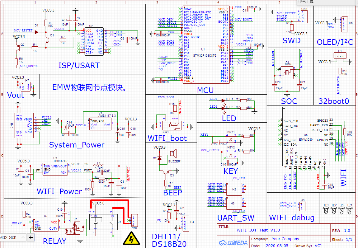
In this design, the main control adopts STM32F103C8T6, LQFP-48 package; WIFI adopts EMW3080, directly connected to Alibaba Cloud; supports manual button opening/closing of the socket (relay); the buzzer is used to prompt the socket action and can also be used for alarm prompts; two LEDs indicate networking status and socket status respectively; it has a temperature/temperature and humidity sensor interface that can detect ambient temperature and humidity; and an onboard I²C interface can be connected to an OLED display or other hardware peripherals.
The STM32 program is responsible for sending and receiving cloud data, button detection, controlling socket on/off, detecting temperature/humidity, displaying data and communicating with external devices (I²C). Use KEIL to program the STM32 program.
There are several key points in the 32 program:
1. Cloud data sending and receiving (packaging and unpacking);
2. Network connection status processing (disconnected, connected);
3. Logical structure;
4. Stability.
Currently, I am writing the 32-end basic function code (LED, button, relay driver, OLED display, temperature/humidity detection), and I am considering which code logic type to use based on the cloud data situation.
The cloud uses Alibaba Cloud's ready-made cloud platform (Feiyan), eliminating the need to build communication links.
The module directly burns the firmware provided by Qingke and configures the cloud through AT commands.
Receive data sent from the cloud and execute corresponding functions based on valid data frames. After the execution is completed, the status data is uploaded to the cloud.
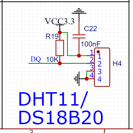
The node board has a DHT11/DS18B20 interface, which can be used by plugging in the sensor. It can detect ambient temperature/humidity and display the data to OLED or upload it to the cloud.
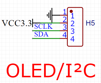
The node board reserves the I²C bus and can mount I²C devices, wireless modules, and microcontrollers (I²C communication).
Refer to the circuit in this training camp to control small-power home appliances (table lamps, incandescent lamps). Relays are used for power conversion, and the microcontroller controls the on/off of the relay to control the on/off of high-current circuits.
The reference design is used directly on the circuit. The relay control pin is controlled by the power switch U6, and the U6 control end is sent to the microcontroller IO through the inverter U7. The power on switch is used here, and the freewheeling diode of the relay coil can be removed.
The on and off of the socket (relay) can be controlled by the KEY1 button or controlled by cloud commands. When the socket is opened/closed, the buzzer sounds to indicate the action status, and at the same time, LED2 indicates the current status of the relay.
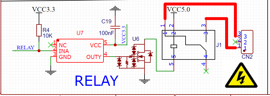
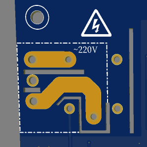
Since some high-current circuits are involved, isolation slots are made on the board to avoid instantaneous electric shock or solder joint ignition when the relay operates.
In the V1 version, the distance between the WIFI module and the relay is relatively close, and there will definitely be problems with long-term use. In subsequent versions, we will consider making the electrical appliances into modules or placing them on the power board.
The V1 version is mainly for debugging and verification. In order to facilitate debugging and safety considerations, a switching power supply board is not added. Subsequent versions will use switching power supply instead of USB power supply and remove the SUB circuit.
The power supply part directly uses USB to input 5V. After filtering, it is divided into four channels, which supply CH340, system power, WIFI power and relay respectively.
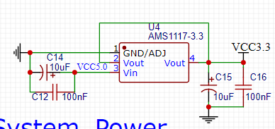
The system power supply adopts AMS1117-3.3 low voltage dropout linear voltage regulator chip, which outputs 3.3V to power the microcontroller and its peripheral circuits.
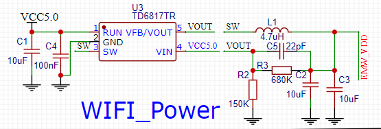
Because the WIFI module consumes a lot of power, in order to ensure its stable operation, a separate power supply is used. The TD6817TR DC-DC chip is used here, with a constant voltage output of 3.3V and a maximum output current of 2A.
CH340C USB to TTL chip is selected, and it is equipped with STM32 automatic download circuit. There is no need to set BOOT when using ISP to download.
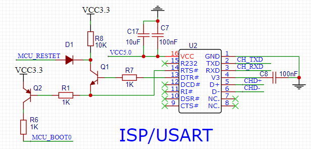
It is not difficult to find out the principle of STM32 automatic download. You can search a lot on Baidu.
In addition to the STM32 download serial port, there are multiple serial ports on the board. In order to facilitate debugging, the serial port used is led out and manually selected with a jumper cap, without flying wires.
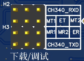
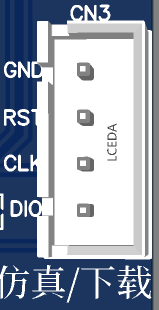
When developing STM32, the debugging code is sometimes simulated using the SWD interface, and compared to the ISP interface, the SWD download speed is faster. It is my personal preference to bring out the SWD interface here.
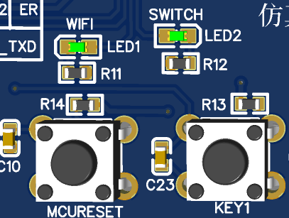
In this design, two touch buttons and two LEDs are used. One button is used to reset the STM32, and the other button is used to configure the WIFI network and control the socket on and off. Two LEDs indicate network status and socket status respectively.
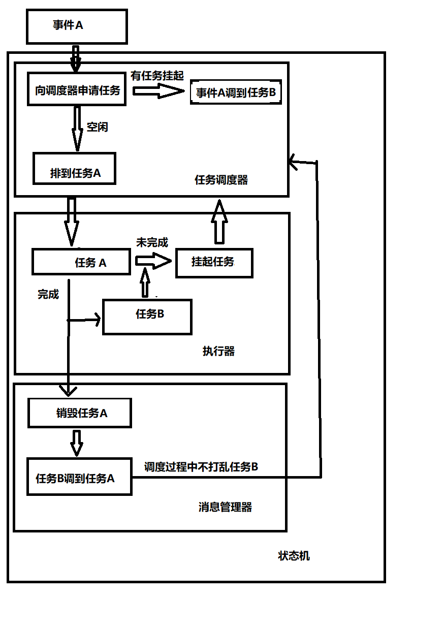
program logic
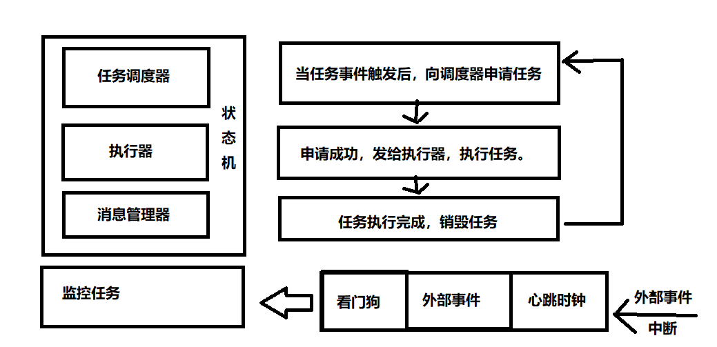
State machine logic

All reference designs on this site are sourced from major semiconductor manufacturers or collected online for learning and research. The copyright belongs to the semiconductor manufacturer or the original author. If you believe that the reference design of this site infringes upon your relevant rights and interests, please send us a rights notice. As a neutral platform service provider, we will take measures to delete the relevant content in accordance with relevant laws after receiving the relevant notice from the rights holder. Please send relevant notifications to email: bbs_service@eeworld.com.cn.
It is your responsibility to test the circuit yourself and determine its suitability for you. EEWorld will not be liable for direct, indirect, special, incidental, consequential or punitive damages arising from any cause or anything connected to any reference design used.
Supported by EEWorld Datasheet
EEWorld
subscription
account

EEWorld
service
account

Automotive
development
community

Robot
development
community

About Us Customer Service Contact Information Datasheet Sitemap LatestNews


Room 1530, 15th Floor, Building B,
No.18 Zhongguancun Street,
Haidian District,
Beijing, Postal Code: 100190
China
Telephone: 008610 8235 0740
 京公网安备 11010802033920号

 177-710-1-9GS4J1-24SCN


