Introduction
With the rapid development of electronic technology, voltmeters and ammeters play a crucial role in electronic measurement, industrial automation, and power monitoring. This report details the design process of a voltmeter and ammeter based on the CW32F030C8T6 model, including functional requirements, hardware design, software implementation, and test results. This voltmeter and ammeter aims to achieve high-precision voltage range measurement.
1. Project Background and Functional Requirements
1.1 Project Background
The CW32 microcontroller is a high-performance microcontroller launched by Chipsource Semiconductor, widely used in embedded systems due to its rich peripheral interfaces, low power consumption, and powerful computing capabilities. This design uses the CW32F030C8T6 microcontroller to develop a voltmeter and ammeter capable of measuring voltage and current and displaying the readings in real time.
1.2 Functional Requirements
Voltage Measurement: Capable of measuring DC voltage in the range of 5V to 99V with an accuracy of 1%.
Current Measurement: Capable of measuring DC current in the range of 0.1A to 3A with an accuracy of 1%.
Real-time Display: Displays voltage and current values in real time via a digital tube.
2. Hardware Design
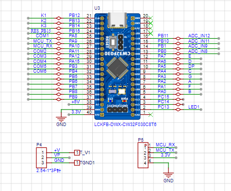
2.1 Main Control Chip Selection
This project selects the CW32F030C8T6 microcontroller as the main control chip. This chip features a high-performance ARM Cortex-M0+ core and rich built-in peripheral interfaces, including ADC, UART, and I2C, meeting the requirements of this project.
2.2 Power Supply Design
Considering that the voltmeter may be used in industrial scenarios with 24V or 36V power supplies, this design uses the SE8533K2 as the power supply chip, supporting a maximum input voltage of 40V. To reduce the heat generation of the LDO under large voltage drops, a small series resistor (10Ω) is added for voltage division. Simultaneously, a separate copper foil area is set under the LDO's heat dissipation pad, and heat is dissipated through vias to improve power efficiency.

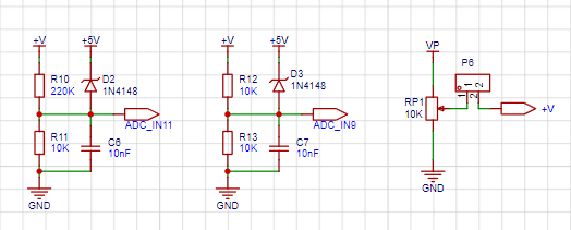
2.3 Voltage Acquisition Circuit The
voltage acquisition circuit uses a voltage divider circuit to achieve high voltage acquisition. The voltage divider resistors are designed to be 680KΩ and 10KΩ, with a voltage division ratio of 69:1 (approximately 0.0145). The voltage value after voltage division is read by the ADC, and the actual voltage value is calculated by the program. Considering the possible fluctuations in the measured power supply, a 0.1uF filter capacitor is connected in parallel with the low-side voltage divider resistor to improve measurement stability.
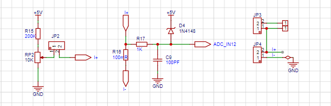
2.4 Current Acquisition Circuit
The current acquisition circuit adopts the low-side current sampling method, and the sampling resistor is connected to the meter ground. According to the maximum value of the designed measured current (3A) and the voltage difference limit of the current sensing resistor (generally not exceeding 0.5V), a 100mΩ sampling resistor is selected. The voltage value on the sampling resistor is read by the ADC, and the actual current value is calculated. Considering the limitations of the surface-mount sampling resistor in high current scenarios, a constantan wire through-hole pad is reserved for replacement according to the actual use scenario.
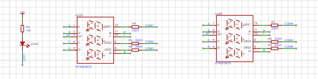
2.5 Display Module
The display module adopts a seven-segment digital tube to display voltage and current data in real time. It has the characteristics of high contrast, low power consumption and fast response, which is suitable for the display requirements of this project.
2.6 Reference Voltage Circuit

3. Software Design
3.1 Main Program Flow
The main program flow includes system initialization, ADC configuration, data acquisition, data processing and display. System initialization includes clock configuration, GPIO initialization, and ADC initialization; ADC configuration includes setting the sampling rate, resolution, and trigger mode. Data acquisition involves reading voltage and current values through the ADC, and data processing includes calculating the actual voltage and current, which are then displayed in real time via a digital tube.
3.2 Data Processing Algorithm
The data processing algorithm mainly includes voltage and current calculations. Voltage calculation is performed by reading the ADC value and multiplying it by the voltage divider ratio to obtain the actual voltage value; current calculation is performed by reading the ADC value and dividing it by the resistance of the sampling resistor to obtain the actual current value. Power calculation is performed by multiplying the voltage and current values.
4. Testing and Verification
4.1 Test Environment
The test environment includes an adjustable power supply, a multimeter, and the circuit under test.
The board for this project was unsuccessful due to soldering issues and is not yet fully debugged. I will start a second round of testing once I raise funds. More updates to follow!


 京公网安备 11010802033920号

 M83421/01-5189S


